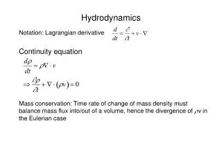
Download

1 / 31
310 likes | 412 Views
Center for Radiative Shock Hydrodynamics. Introductory overview R. Paul Drake. We will take you from overviews to specifics. This first presentation Motivation and introduction to the physical system Overview of the experiments and of the project Overviews this morning

E N D
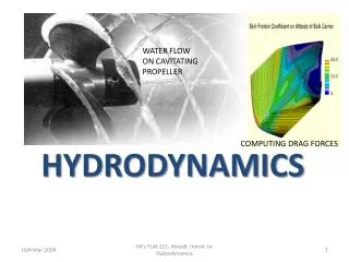
Center for Radiative Shock Hydrodynamics Introductory overview R. Paul Drake
We will take you from overviews to specifics • This first presentation • Motivation and introduction to the physical system • Overview of the experiments and of the project • Overviews this morning • Powell on the simulation • Holloway on assessment of predictive capability • Code and verification this afternoon • Toth on architecture and practices • Myra on tests • Assessing predictive capability in the morning • Bingham on our first integrated study • Fryxell on 3D sensitivity runs • Posters today • See the details and meet the people • You will see how our priorities have been driven by becoming able to assess the capability of our code to predict our year 5 data.
We find our motivation in astrophysical connections Ensman & Burrows ApJ92 • Radiative shocks have strongradiative energy transport that determines the shock structure • Exist throughout astrophysics • Supernovae, accretion, stars, supernova remnants, collisions • Our experiments • have behavior and dimensionless parameters relevant to shocks emerging from supernovae • We should see any important unanticipated physics • Good code test in any event Reighard PoP07
A brief primer on shock wave structure • Behind the shock, the faster sound waves connect the entire plasma Denser, Hotter unshocked shocked Shock velocity, us Initial plasma Mach number M > 1 Mach number M = us / csound
Shock waves become radiative when … • radiative energy flux would exceed incoming material energy flux where post-shock temperature is proportional to us2. • Setting these fluxes equal gives a threshold velocity of 60 km/s for our system: Ts4ous3/2 unshocked preheated shocked Material xenon gas Density 6.5 mg/cc Initial shock velocity 200 km/s Initial ion temperature 2 keV Typ. radiation temp. 50 eV
The CRASH project began with several elements • An experimental system that is challenging to model and relevant to NNSA, motivated by astrophysics • A 3D adaptive, well scaled, magnetohydrodynamic (MHD) code with a 15 year legacy and many users • A 3D deterministic radiative transfer code developed for parallel platforms • A strong V&V tradition with both codes • Some ideas about how to approach “UQ” in general and specifically the Assessment of Predictive Capability Space weather simulation
CRASH builds on a basic experiment • Basic Experiment: Radiography is the primary diagnostic. Additional data from other diagnostics. A. Reighard et al.Phys. Plas. 2006, 2007 F. Doss, et al. HEDP, submitted 2009 Grid Schematic of radiograph
We have identified key parameters for the code/experiment comparison • Key measurements at data time • Basic (1D) • Shock position • Layer thickness • Multi-D • Distance of kink in shock from tube wall • Angle of xenon edge just downstream of shock
Our experimental sequence will improve and test our assessment of predictive capability • A conceptually simple experiment • Launch a Be plasma down a shock tube at ~ 200 km/s • Year 5 experiment • Predict outcome and accuracy before doing year 5 experiment • Goals • Improve predictive accuracy during project • Demonstrate a predictive uncertainty comparable to the observed experimental variability • A big challenge and achievement
Last April we reported a CRASH 1.0 3D simulation of the year 5 experiment Initialized by calibrated laser code, to be discussed by Ken Top view Side view Density Temperature 2008 IRT: The project will live or die based on whether a “reasonably good code” can be built This font color highlights responses to 2008 IRT recommendations
The CRASH research process incorporates many UQ elements. Culture change is here.
UQ considerations have driven the project to date • Had to become able to Assess Predictive Capability • Develop a “reasonably good” code • Code tests and physics tests • “Drill-down” documentation system • Variability of base experiment (10/08) • Early data to calibrate inputs (12/09) • Learn enough to define the CRASH UQ methodology • Tests of UQ methods • We are using the tools we have assembled • Going forward, UQ analysis must tell us what code to write, what experiments to do, and what UQ to do • Working independently on additional diagnostics • X-ray and imaging Thomson Scattering
We are organized to bring leadership and effort to all areas where they are needed • Most of our team members participate in more than one area (details in supplementary material) • We use our resource plan, our work plan, and UQ considerations to inform priority decisions
We have expanded our theoretical work • The IRT recommended more effort in analytic theory • Paul Drake has invested more time • Enabled by contributions by Ken Powell and James Holloway • Ryan McClarren has a paper on the structure of this type of radiative shock in draft form. • Rob Lowrie (LANL) has collaborated on this. • Graduate student Forrest Doss continues to work on the analytic theory of the shocked layer instability • Igor Sokolov has contributed considerably • Emilio Minguez (U.P. Madrid) has visited for opacity collaborations • We are working to engage Dmitri Ryutov (LLNL) and Sasha Velikovich (NRL), who are interested • We have a CRASH primer which will evolve
CRASH will have other applications and users • Solar group is already doing rad-MHD evolving from CRASH • Our experiment team (students funded variously) needs CRASH • Already one other university is eager to use our code (FSU) • The labs will be users of our trained people more than codes • Our NIF team may become a key user • Experimental program is making first university use of NIF • Excellent opportunity to apply CRASH and see what breaks CRASH simulation of NIF Radiative Hydrodynamic Instability experiment at 7.0 ns: 2D, 600 x 80
We intend to accomplish an important result • Our unique intended contribution • Be the first academic team to use statistical Assessment of Predictive Capability to guide improvements in simulations and field experiments that lead to predictions of extrapolated field experiments known to have improved accuracy, and to demonstrate this by field measurements. • This is a sensible goal because • Our codes are almost entirely first-principles calculations • Our approach will be to add physics not tuning
Supplemental material follows • More details
Conservation of energy forces the shock wave to develop complex structure Shocked xenon layer Compressed 40x Traps thermal photons Preheated region Thermal photons escape upstream Other fun complications: Instabilities Wall shocks
Our experiments are at the Omega laser • Related experiments • LULI & PALS & RAL, LIL (soon?) • NIF & LMJ maybe someday One of our shots at the Omega laser • Omega • 60 beams • 30 kJ in 1 ns • 0.35 µm wavelength
How to produce radiative shocks • Laser beams launch Be piston into Xe or Ar gas at > 100 km/s • Piston drives shock • Diagnostics measure plasma properties • Gold grids provide spatial reference • Parameters • 1015 W/cm2 • 0.35 µm light • 1 ns pulse • 600 µm tube dia. Gas filled tubes Targets: Korbie Killebrew, Mike Grosskopf, Trisha Donajkowski, Donna Marion Experiments: Amy Reighard, Tony Visco, Forrest Doss
The laser first creates structure at the target surface • The laser is absorbed at less than 1% of solid density Ablation pressure from momentum balance: Typical pressures of tens of Mbars p ~ 8.6 I142/3 / µm2/3 Mbars Radiative shocks need thinner targets than the one shown here From Drake, High-Energy-Density Physics, Springer (2006)
For radiative shocks, target acceleration produces the high required velocities Laser produced pressure accelerates Be plasma • Profiles at 1.3 ns shown Acceleration pushes velocity into radiative shock regime Expanding Be drives shock into Xe gas
Researchers are studying these shocks with a range of diagnostics and simulations • Radiographs Emission Interferometry Xray Thomson scattering Data credits: L. Boireau S. Bouquet, F. Doss M. Koenig, C. Michaut, A. Reighard, T. Visco , T. Vinci
Radiography is our workhorse; we also use other diagnostic methods X-ray Thomson Scattering Transverse Streaked Optical Pyrometer (SOP) UV Thomson Scattering Radiographs (1 or 2 views) Data by grad students Amy Reighard (Cooper), Tony Visco, Forrest Doss, Channing Huntington Christine Krauland Transverse VISAR
Preliminary analysis of XRTS obtained reasonable temperatures but a better model of Z is needed Precursor Cooling Layer Null Shot • 15ns delay • Scattered from radiative pre-heated region • Fit gives Te = 10 eV & Zfree = 12 • 19ns delay • Scattered from dense cooling region • Fit gives Te = 55 eV & Zfree = 14 • No drive beams, Null shot • Zfree = .2 Data and fits by Tony Visco
Lateral structure within the shocked layer is expected from a Vishniac-like mechanism. See E. Vishinac, ApJ 1983
Theoretical analysis shows structure internal to shocked layer for the experimental case • Wavelength and growth rate of instability in reasonable agreement with observations • Stereoscopic experiments will seek further evidence Unperturbed system Perturbed system Vorticity features Be Z = H . Shocked Xe U -Vs Z = 0 Vs Unshocked Xe Forrest Doss, et al. in preparation
Simulating these shocks is challenging but not impossible • Optically thin, large upstream • Electron heating by ions • Optically thin cooling layer • Optically thick downstream • This problem has • A large range of scales • Non-isotropic radiation • Complex hydro 20
The CRASH project has evolved over its first 18 months Project status at day zero: To do UQ, needed “reasonably good code” and experimental data on variability and for calibration Fall 2008 CRASH 1.0 beta Expand UQ team Variability Expt Hire 2 FTE + Spring 2008 Funds arrive Code planning Recruiting Summer 2008 CRASH 1.0 tasks First sensitivity Winter 2009 CRASH 1.0 frozen 3D Yr5 simulation UQ methods exploration Spr/Sum 2009 CRASH 2.0 Tasks UQ on UQ First end to end UQ 3rd hire (expts) Fall 2009 expectation CRASH 2.0 beta 3D CRASH sensitivity Define 2D UQ study Calibration experiment