Download
1 / 30
330 likes | 700 Views
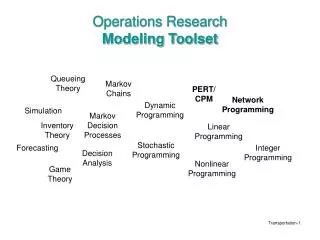
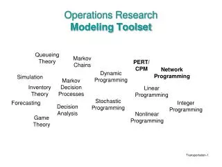
Research Repot on A123 Battery Modeling. Task 4 Members: Faculty: Dr. Mo-Yuen Chow, Dr. Srdjan Lukic Research Assistants: Lei Wang, Arvind Govindaraj. Presentation Outline. Research Objectives Battery Properties Battery Model Future Research. Research Objectives. Battery Modeling

E N D
Research Repot on A123 Battery Modeling Task 4 Members: Faculty: Dr. Mo-Yuen Chow, Dr. Srdjan Lukic Research Assistants: Lei Wang, Arvind Govindaraj
Presentation Outline • Research Objectives • Battery Properties • Battery Model • Future Research
Research Objectives • Battery Modeling • Develop Charging Algorithms
Presentation Outline • Research Objectives • Overview of battery properties • Battery Model • Future Research
PHEV Battery Operation Modes • Charge-depleting mode: vehicle uses battery power until SOC reaches a predetermined level • Charge-sustaining mode: uses both battery and engine power • Blended mode: charge-depleting mode with engine power to reach high speed Ex. 90% of time discharging, 10% charging Ex. 30% discharging, 70% charging
A123 Lithium Ion ANR26650M1 25C, C/30 < 20A tested SoH ANR26650M1 Datasheet AUGUST 2008
A123 Lithium Ion ANR26650M1 Not available • Operating range: -30c to 60c • Performance under different temperatures was not tested • Discharge curve shape changes at extreme temperatures, thus may not be described by model equations • Maximum discharge: 70A • Model may fail at high discharge current due to irregular shape of the discharge curve First Step: Have a model that satisfies the nominal condition
Quantify Battery • State of Charge (SoC): 100% > SoC > 0% • SoC = (remaining capacity) /(capacity of fully charged battery) • SoC = (remaining capacity) / (Total amount of usable charge at a given C-rate) • SoC = (Cn – Qb) / Cn • Cn: nominal capacity • Qb: net discharge • Remaining Capacity ≠ Usable Capacity • Usable capacity depends on the cutoff voltage • Usable capacity depends on the age of the battery • Capacity of fully charged battery ≠ Total amount of usable charge at a given C-rate ≠ Cn (C/30) 8
Usable Capacity Discharge Rate = 1A 7738s x 1A / 3600s = 2.149Ah Discharge Rate = 5A 1537s x 5A / 3600s = 2.136Ah T=1537s T=7738s Discharge Rate = 10A 1389s x 10A / 3600s = 2.1215Ah Discharge Rate = 20A 683s x 20A / 3600s = 2.098Ah T=683s T=1389s 9
Usable Capacity vs Discharge rate Rated Capacity at 2.3Ah (using C/30 discharging rate) 10
Quantify State of Health (SoH) • Full Discharge Test (SOH) • SoH = (measured capacity) /(rated capacity) • 1 > SoH > 0 A battery is at its end of lifetime at SoH of 0.8 .(Energy Institute Battery Research Group) • Increase in internal resistance resulting active power loss • Increase in self discharge • Counting charge/discharge cycles • Voltage drop during initial discharge • Two-Pulse Load Test 11
State of Function (SoF) • Capability of the battery to perform a specific duty which is relevant for the functionality of a system powered by the battery. • For example: Use 20A to discharge a battery • after 683s battery reaches the cutoff voltage 2v • Battery still has the capacity left to be discharged by 10A • SoF is a function of the battery’s SoC, SoH and operating temperature. 12
Presentation Outline • Research Objectives • Battery Properties • Battery Model • Model results and analysis • Future Research
Discharging Results 1A 5A 10A 20A
Battery Model Zk: State of Charge ηi: Cell Coulombic efficiency (Eta = 1 for discharge) Cn: Cell nominal capacity Δt: sampling period Yk: Cell Terminal Voltage Shepherd model: yk = E0 − Rik − Ki/zk Unnewehr universal model: yk = E0 − Rik − Kizk Nernst model: yk = E0 − Rik + K2 ln(zk) + K3 ln(1−zk) Least Squared Fit: [Y] = [K]*[A] [A’][Y] = [K]*[A][A’] Matlab: k = (inv(A'*A))*A'*Y Gregory L. Plett, University of Colorado at Colorado Springs, Extended Kalman filtering for battery management systems of LiPB-based HEV battery packs Journal of Power Sources 134 (2004) 252–261
Constant Current Discharging @ 20A, 10A, 5A, 1A Y: observed data F: model data R2_01A = 0.99R2_05A = 0.97R2_10A = 0.93R2_20A = 0.85
Voltage Error: Actual voltage – estimated 1A: <0.05V 5A: <0.07V Error is very small Usually don’t fully discharge or charge the battery 10A: <0.07V 20A: ~0.3V
Model 20% - 80% of SOC • At a low state of charge: nearly all the charging current is absorbed by the chemical reaction. • Above 80% of SOC, more and more energy goes into heat. • reduce current for the last 20%
Measured Zoomed in
Interval Discharge 5A for 60s & 20A for 30s Purpose: When driving, different discharging currents are applied to the battery
Hysteresis • Hysteresis slowly changes as the cell is charged or discharged • Hysteresis is considerably larger at low temperatures.
Modeling hysteresis effect • constant γ tunes the rate of decay • M is a function that gives the maximum polarization due to hysteresis as a function of SOC and the rate-of-change of SOC.
Relaxation effect • If a cell is pulsedwith current, it takes time for the voltage to converge to itssteady-state level. • Relaxation effect may be implemented as a low-pass filter on ik • The output equation had the form:
Future Work • Pulse Discharging • SoH, SoF • Charging Algorithms • Optimum power usage
Acknowledgement Please use one of the following three languages • This work was supported by ERC Program of the National Science Foundation under Award Number EEC-08212121. • This work made use of ERC shared facilities supported by the National Science Foundation under Award Number EEC-08212121. • This work was partially supported by the National Science Foundation (NSF) under Award Number EEC-08212121.