Download
1 / 45
460 likes | 612 Views
SPACE DETECTORS TUS and KLYPVE for STUDY of ULTRA HIGH ENERGY COSMIC RAYS. TALK AT THE INTERNATIONAL SEMINAR ON ULTRA HIGH ENERGY COSMIC RAYS 14 APRIL 2005 B. A. KHRENOV D.V. Skobeltsyn Institute of Nuclear Physics

E N D
SPACE DETECTORS TUS and KLYPVE for STUDY of ULTRA HIGH ENERGY COSMIC RAYS TALK AT THE INTERNATIONAL SEMINAR ON ULTRA HIGH ENERGY COSMIC RAYS 14 APRIL 2005 B. A. KHRENOV D.V. Skobeltsyn Institute of Nuclear Physics of the Moscow State University, Moscow, Russia
How Extensive Air Showers are measured EAS cascades for primary energy 1018 eV. Red curve- primary iron nuclei. Dotted blue- primary proton. Extensive Air Showers (EAS) give information on Cosmic Rays starting from energies 1014-1015 eV. At energies more than 1018 eV the EAS atmosphere fluorescence is measured along with the particle flux and the Cherenkov light. Fluorescence Particle or Cherenkov Detector detectors The isotropic fluorescence radiation could be measured from space - from satellites. The innovative technology of space fluorescence detectors is in progress.
Methods of the EAS primary energy measurement • Successfully working methods: • Charge particle (electron) size. Integral over the experimental lateral distribution. Core distances ~100 m. • Charge particle density at large core distance ~600-1000 m. • Air Cherenkov radiation flux in air (in water). • Atmosphere fluorescence signals (cascade curve, signal at the EAS maximum). • Other methods, less certain : • Radio signal, radiated by EAS (Cherenkov, geo-magnetic mechanisms) in air, in ice. • Acoustic signals in ice and water, in the Moon ground. • Radio echo from the EAS core.
Scientific Problem - Origin Of The Ultra High Energy Cosmic Rays (UHECR) Experimental data ofAGASA are against the GZK Cosmic Ray cut off. Data of HiRes confirm the cut off. Yakutsk data agree with the HiRes data. Detectors of the next generation should solve the problem.
What is the cut off? G.T. Zatsepin (1967) Greisen-Zatsepin-Kuzmin made the first estimates of the effect and find the energy limit for protons EGZK =5x10¹⁹ eV. P+γ=P+hadrons Eγ=2Eph Ep /Mp c2 Eph =2.5 10-4 eV (T=2.75K) In proton rest frame photon energy Eγ >100 MeV for Ep >1020 eV. ρph=500 cm-3 Cross-section of interaction is σ=10-28 cm2 Interaction free path L=1/ σ ρph =70 Mpc
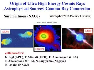
Arrival direction of UHECR particles over the Northern hemisphere. Red squares- E>1020 eV, green points- E=4-10 1019 eV. Dublets and triplets (events from the same coordinates in sky in errors of 2.5o) are blue and violet circles. Galactic (red) and Supergalactic (blue) planes are presented as curves.
Possible sources: astrophysical accelerators, the objects with the relativistic shocks.
The alternative sources of EECR are the massive particles (M~1024 eV) – relics of the Big Bang. They might be responsible for the Dark Matter. The EECR protons (or gamma quanta) are products of their decay. The EECR particles registered by AGASA in this interpretation indicate the Dark Matter of our Galaxy. Topological defects are the other theoretical source of the massive particles decaying to EECR particles. The experimental separation of photons from protons in EECR is the key point in a search for massive particles, producing mainly photons in final decay generation. AGASA data on the muon to electron ratio in EAS of the highest energies are against the photon origin of primaries.
r Ground based fluorescence detector has a problem of fluorescence light absorption in a horizontal view. Absorption length La as a function of the fluorescence wavelength at sea level. La is the result of the Rayleigh scattering. Sometimes scattering on aerosols makes Lreal<<La. At horizontal distance r~30 km to the EAS disc the fluorescence photon intensity decreases by 10 times due to Rayleigh absorption . Aerosol absorption may make it order of magnitude less.
The space fluorescence detector looking to the atmosphere from a larger distance (400 km) should have larger light collection mirror but it has advantage of low light absorption in the atmosphere. This advantage makes it possible to have reliable EAS fluorescence signals in the detector with a comparatively small mirror: ~10 m2 . Percentage of light escaping the Rayleigh scattering in the atmosphere (vertical direction).
The inclined EAS’s (zenith angles >50o) are developed high in the atmosphere, above the clouds, where the atmosphere is highly transparent and stable. The Cherenkov light scattered from the clouds at reference height provides the absolute scale of height in the atmosphere for observation from a satellite. The cloud height has to be measured by a special device (Lidar) immediately after the EAS event registration.
In 1980 Prof. John Linsley suggested to put the fluorescence detector into space and look down to the Earth atmosphere. He called this experimental concept - “Airwatch”. He initiated two parallel space projects: wide angle optics (OWL, EUSO) and large mirror optics (KLYPVE, TUS). In 2000 at the Lodz European symposium he gave a talk “Beyond the GZK horizon” stressing the point of detection of EAS, generated in the atmosphere by the secondary (cosmological) neutrino with energy threshold of 10 EeV. At that time only KLYPVE project with 10 m2 mirror was being developed to register such a “low” energy EAS.
KLYPVE is a narrow FOV detector (“telescope”) with a large area mirror-concentrator. What advantages the telescope has compared to the OWL-EUSO wide FOV detectors? • Large mirror makes possible to detect UHECR already measured with the ground-based detectors (calibration of the space detector method). • When mirror area is enlarged up to 100 m2 (energy threshold 3EeV), the telescope observing the area of 104 km2 will let us measure the anisotropy of CR in the energy range 3-10 EeV where the transition from Galactic to extragalactic origin is expected . • Low energy threshold will help to look beyond GZK horizon registering “cosmological” neutrinos. • Development of the large mirror-concentrator technology is of great interest for space researches. A reliable, large area mirror- concentrator is easier to construct than the complex lens optics. • 5. For example, when the mirror area is enlarged to 1000 m2 , it will be possible to register EAS and other optical flashes almost at the whole atmosphere disc with a telescope in a geostationary orbit.
1000 m2 telescope at the geostationary orbit. Mirror diameter 30 m, resolution 16 arc sec (3 km in the atmosphere). Energy threshold 1020 eV. Observed area 3x10⁷ km2.
How to build a large mirror-concentrator in space? • There were many suggestions: • Standard segmented parabolic • (spherical) mirror. • 2. Inflatable concentrator. • 3. Fresnel “high frequency” mirror. • 4. Fresnel “low frequency” mirror. • We have chosen the option of the • segmented “low frequency” • Fresnel mirror. • Our Cosmic Ray • experimental device • is an additional payload • in the planned ROSCOSMOS • missions. • Our device has to be compact in transportation mode.
Design of the segmented mirror- concentratorconsisted of 37carbon- plastic segmentsof the low frequency Fresnel mirror. • The mirror- concentrator mass is less than 50 kg for the mirror area of 10 m2. • Accuracy in mirror ring profiles 0.01 mm. • Stability of the mirror construction in the temperature rangefrom –80oto + 60oC. • The mirror development mechanism makes the mirror plane with the angular accuracy less than 1 mrad.
The first mirror telescope is an additional payload at the RESURS DK-1 mission (planned to be next after the Pamela experiment). The TUS (Tracking Ultraviolet Set Up) detector registers an EAS track from the Space Platform. The light collector and photo detector are highlighted in red.
The other option of the TUS accommodation on the next RESURS platform: Resurs O. 2 ТUS telescopes register the EAS track from Resurs O. Independent registration by two telescopes will allow to check errors in the EAS parameters.
Photo receiver concept: • The pixel size at the atmosphere has to be 1-3 km • (a compromise between needed 1 km resolution and • economical number of pixels). • 2. For large mirror diameter with a focal distance equal • to the diameter (condition of small aberrations) the • pixel size in the focal plane is rather large (>1cm) and • a single PM tube (not the multi-anode tube) is the best • photo sensor. • 3. Pixel photo sensor has to be robust, operating linearly in • wide range of the atmosphere luminosity (moon nights included). • 4. Photo sensor should be stable in at least 3 years of operation • in space.
Photo sensor: 1.reflecting light guide 2. PM tube 3. Raw of sensors with the electronic board (4) under it. 6. The photo receiver box covered by UV filter (8) and the blend 7 (protection from side light).
Example of the EAS, “registered” by the telescope Concept of the UHECR registration- many channel digital oscilloscope E0=100 ЕeV, θ0=75°, φ0=25°, Moonless night;σE0/ E0 ~ 10 %, σθ0 ~ 1.5°, σφ0 ~ 1°.
Organization of work on the space UHECR telescopes. Russia team. ROSCOSMOS - the Operator. SINP MSU- the Leading Institution. Participants: JINR (Dubna) RSC “ENERGIA”, Consortium “Space Regatta”. Samara “PROGRESS” Construction Bureau. KOSMOTEPETL COLLABORATION. Russian team Mexican Universities: Puebla (BUAP), Michoacan. Korean University (Seoul).
The first TUS telescope parameters • Area of mirror-concentrator- 1.4 m2 • Focal distance - 1.5 m • Pixel number - 256 • Pixel size (FOV) - 1.5 cm (0.01 rad) • Detector FOV - 0.16 rad • Time sampling from - 800 ns • Wave length range -300-400 nm
Two TUS detectors on board of the Resurs O. • The TUS detector on board of the Resurs DK1
Steel press-forms for production ofcarbon plastic mirror replicas (JINR).
The mechanism of mirror development is designed (Consortium Space Regatta) In this mechanism one electric motor moves the segments via axles and Cardan joints.
The TUS photo receiver prototype: 4x4=16 PM tubes. It was tested in the Puebla University (Mexico).
TUS prototypes at the Mexican mountains Mexican Universities team with the first TUS prototype A view from the TUS mountain site
The TUS Project Scientific Goals. 1. Proofing the new technology of EAS observation by the Space Detector. 2. Experimental study of the Cosmic Ray energy spectrum in the range of energies>50 EeV with the geometrical factor not less than 3 000 кm2srper yearwith the EAS energy threshold of 30-50EeV. 3. A search for “exotic” EAS with Xmax >1200 g/cm2 (initiated by neutrino) and with Xmax <300 g/cm2 (initiated by relativistic dust grains). 4. UHECR anisotropystudy. 5. A search for other phenomena of UV atmospheric flashes. 6. Testing the TUS mirror-concentrator design in view of using it for construction of large area mirrors in space (up to 100 m2 ).
Energy spectrum of EECR expected as a result of the TUS operation in 2 years. 1- as predicted by data of Yakutsk and HiRes, 2- as predicted by data of AGASA.
Expected distribution of EAS maximum positions for various primaries. 1- relativistic dust grain, 2- iron nucleus, 3- proton, 4-Fly’s Eye experimental data for energy 1019eV, 5- neutrino.
The TUS type UV detector at the MSU “Tatiana” satellite UV detector comprises 2 PM tubes (one tube measures the charge particle background) and electronics block. Detectors on the micro satellite. Goals in 2005: Testing the PM tubes and the TUS type electronics. Measurement of the atmosphere UV background in short time samples (0.1 msec). Measurements of aurora lights, meteors, lightnings.
“Tatiana” is orbiting the Earth at approximately circular polar orbit with the height of 1000 km. Diameter of the observed atmosphere is 250 km. Several types of UV measurements: 1. Every 4 sec ACD measures the PMT charge collected in integration time 60 msec. (measurements of UV on-route) 2. Digital oscilloscope measures the UV flashes with time sample 16 µs (duration <4 msec). 3. Digital oscilloscope measures the UV flashes with time sample 256 µs (duration <64 msec). In 2 and 3 only the brightest events are sent to the mission center (problem of poor telemetry).
Examples of UV intensity measurements on- route. Moonless night. A peak at right is the Japan UV lights.
The moon night. The UV intensity depends on the moon phase and its height above the local horizon. There is a correlation of UV intensity with the cloud regions (preliminary analysis). The registered range of UV intensity at the night side of the Earth is 2x10⁷ -3x10⁹ photons/cm2 sec sr
Examples of short UV flashes. Below are data from 6 circulations in one day. In two of them UV flashes are registered. Due to recording conditions many of flashes have saturated signals. Energy of saturated UV flashes in the atmosphere is >10KJ. Their duration: 1-2 ms.
Geographic coordinates of the short UV flashes correlate around the equator. In the same region the IR measurement (right panel) indicates heavy clouds (may be thunderstorms). Looks like UV detector registers the blue jets (discharges between clouds and mesosphere)
The phenomenon of blue jet is incomparably brighter than the EAS of 100 EeV energy. For registering blue jets the gain in the TUS pixels should be much less than needed for the EAS observations.
The other phenomenon to be detected in the TUS detector are meteors. Entering the atmosphere with the velocity of 30 km/s they ionize the atmosphere and excites the fluorescence. Expected signal in TUS with the “slow” digital oscilloscope is shown below:
Similar but faster signals are expected from the fast dust grains. Dust grains, entering the atmosphere with the velocity of ~109 cm/s, are expected from the 104 year old SN’s (Khrenov&Tsytovich, 2005).
3 Spectrum of the meteors over their kinetic energy. 1 - average intensity of solar meteors, 2 - expected spectrum of the extra-solar meteors, 3 - experimental points are data on extra-solar meteors from radar measurements Bold lines- expected results from the TUS telescope. Bold circle - the rate of fast grains from old SN’s. At the lowest intensity (10-9) the rate in TUS is hundred events per year.
Conclusion • In phase A of the TUS project the segmented 1.4 m2 mirror-concentrator is designed. The goal of this design is to construct large space mirrors with area up to 10-100 m2 . • Electronics of the TUS photo receiver (256 pixels) is designed and tested in operation of the Tatiana satellite. This design could be applied in construction of the photo receiver of the next KLYPVE telescope. • The TUS telescope is able to study other phenomena in the atmosphere by measuring fluorescence images of -Blue jets, lightning -Micro meteors -Fast dust grains. • The TUS electronics is suited for registering these “slow” flashes. The TUS triggering conditions will be controlled from the mission center. • The TUS phase B has to be started in 2006.