A 1
250 likes | 276 Views
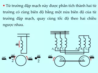
B 1. C 1. A 2. A 1. B 2. C 2. n. n. Từ trường đập mạch này được phân tích thành hai từ trường có cùng biên độ bằng một nửa biên độ của từ trường đập mạch, quay cùng tốc độ theo hai chiều ngược nhau. Như vậy trong máy không có từ trường quay nên không có mô men quay.

A 1
E N D
Presentation Transcript
B1 C1 A2 A1 B2 C2 n n Từ trường đập mạch này được phân tích thành hai từ trường có cùng biên độ bằng một nửa biên độ của từ trường đập mạch, quay cùng tốc độ theo hai chiều ngược nhau.
Như vậy trong máy không có từ trường quay nên không có mô men quay. Nếu roto được quay theo chiều nào đó(bằng tay chẳng hạn) như hình bên, các thanh dẫn roto sẽ cắt qua d Trong thanh dẫn roto sẽ xuất hiện s.đ.đ và dòng điện. Dòng điện này tạo ra từ thông q. d gọi là từ thông dọc trục và q – từ thông ngang trục.
d q t 45o 0o 315o 180o 225o 90o 270o 135o Quan hệ về pha của d, d và s.đ.đ: Như vậy quay roto sẽ tạo ra từ trường ngang. Từ trường này kết hợp với từ trường dọc trục sẽ tạo ra từ trường quay theo hướng quay ban đầu. Từ trường này gia tốc roto lên đến tốc độ gần n1.
Xf Xc Rf Rc PS Phase splitter 3. Động cơ phân pha Để tạo ra từ trường quay cần có 2 dây quấn stato và một thiết bị phân pha.
Dây quấn chính tạo ra d còn dây quấn phụ đặt lệch 90o điện so với dây quấn chính sẽ tạo ra q. Dây quấn phụ gọi là dây quấn. The phase splitter is connected in series with the auxiliary winding and causes the current in the auxiliary winding to be out of phase with the current in the main winding. The splitter is normally resistance or capacitor.
4. Locked-rotor torque The locked-rotor torque of a split-phase motor is proportional to the product of the magnitude of the locked-rotor current in each winding times the sin of the angle of phase displacement between two currents. Expressed mathematically: Ic – current in main winding If – current in auxiliary winding
Example: The main and auxiliary windings of a 220V, 50Hz split-phase motor have the following locked-rotor parameters: Rc = 3.94, Xc = 4.2, Rf = 8.42, Xf = 6.28. Determinate locked rotor current in each winding, phase-displacement angle between two currents, locked-rotor torque, external resistance required in series with the auxiliary winding in order to obtain a 30o phase displacement between the currents in the two windings
The impedances of the two windings: Currents in the two windings: Phase displacement angle between the currents in the two windings:
Zf Xf Rf + Rx = 46.83o – 36.71o = 10.12o Locked-rotor torque: Mmm = k20.8411.42sin10.12o = 41.82k In order to obtain a 30o phase displacement between the currents in the two windings the phase angle of the current in the auxiliary winding If must be: = 46.83o - 30o = 16.83o
With the auxiliary resistance Rf, the current If is: And the locked-rotor torque in this condition is: Mmm = k20.845.5327sin16.38o = 32.52k
Main winding Aux. winding 5. Resistance-start split-phase motor • The circuit diagram for resistance-start motor: • The auxiliary winding is wound with smaller diameter wire than the main winding, causing the auxiliary winding to have a higher ratio of resitance to reactance than the main winding.
Main winding Aux. winding • The switch in the auxiliary circuit is magnetic relay, a solid-state switch or a centrifugally operated switch. • A representative phase diagram for the motor is shown in the next figure.
M Main winding s C Aux. winding • The torque-speed characteristic is shown in the next figure 5. Capacitor-start split-phase motor • The circuit diagram of the motor is shown in the fig.: • The phase-displacement between the currents is performed by capacitor C.
M s • A phasor diagram and torque-speed characteristic for the motor is as follows: • With the capacitor, = (77 88)o then the locked-rotor torque greater than the one of the resistance-start motor.
Example: The main and auxiliary windings of a 220V, 50Hz split-phase motor have the following locked-rotor parameters: Rc = 3.94, Xc = 4.2, Rf = 8.42, Xf = 6.28. Determinate the capacitance required in series with the auxiliary winding in order to obtain a 90o phase displacement between the current in the main winding and the current in the auxiliary winding at locked-rotor.
The impedances of the windings: The current in the main winding: The current in the auxiliary winding:
46.83o For the capacitance in series with the auxiliary winding , to obtain the 90o phase displacement, the phase angle of the current in the auxiliary winding must be: = 90o – 46.83o = 43.17o
The current in the auxiliary winding If: Locked-rotor torque is : Mmm = k20.8419.06 = 397.2k 5. Shaded-pole motors •The shaded-pole motor utilizes a short-circuited coil or copper ring, called shading coil.
n c •This coil wound around a part of the pole face. •The current flow in the stator winding and produces a magnetic flux in poles: c - magnetic flux don’t pass through the short-circuited turn n - magnetic flux pass through the short-circuited turn
n induces in the shading coil a e.m.f En In the shading coil appears a current In. This current creates a flux s The resultant flux through the shading coil is is shifted in time relative to c an angle of and in space an angle of . Therefore in the air gap there is a ellipse rotating magnetic field.
6. Operation of three-phase induction motors from single-phase lines • Sometimes, three-phase induction motors can oprerate from single-phase lines. • We can use the circuit diagram as follows: • Normally we use: C1 + C2 230F/hp C1 26.5F/hp
C1 –running capacitance C2 –starting capacitance 7. Single phasing(a fault condition) • Single phasing is a fault condition in which a three- phase motor is operating with one line open. • If motor is running when single phasing occurs, it will continue to run as long as the shaft load is less than 80 percent rated load and remaining single-phase is normal.
• Assuming that the A line is opened and the shaft load remains the same when single phasing as when operating three phase: • The current for this fault condition: • Thus, for the wye connection, the phase current and the line current are the same: IA = 0 IB = IC = I1f
• For delta connection: • If single phasing occurs while operating at or near rated load, the increase in phase current will cause rapid heating of the winding. • Therefore, protective devices must be provided to trip the machine from the supply lines or severe damage to stator and rotor winding may be occur.