Download
1 / 56
560 likes | 679 Views
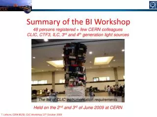
CLIC Workshop 2009. Summary of WG5 Technical Systems Hermann Schmickler – CERN Grahame Blair –Physics Department. Subjects:. Beam instrumentation Module design and integration Quadrupole (MB + FF) stability, BBF partially treated in the summary of A.Seryi Machine Protection

E N D
CLIC Workshop 2009 Summary of WG5Technical Systems Hermann Schmickler – CERNGrahame Blair –Physics Department
Subjects: • Beam instrumentation • Module design and integration • Quadrupole (MB + FF) stability, BBF partially treated in the summary of A.Seryi • Machine Protection • MB-DB phase alignment • Many Others It is impossible to mention in detail the contribution of everybody in this summary. I try to highlight new evolutions and I will point to problem areas that need follow up.
CLIC 3TeV – Numbers of devices CLIC Drive Beam 54580 devices Main Beam 8292 devices + 142812 wakefield monitors T. Lefevre
CLIC BPM overview A total of 52813 BPMs!!...or ~800MCHF CLIC09 Workshop 12-16 October 2009 Drive beam BPM’s Lars Søby 5
Summary of Cavity BPMs in ATF2 Beamline The Thermal noise of the cavity BPMs corresponds to 4nm resolution for a 1e10 intensity electron beam. But, we expect that the noises are amplified by the amplifier in the readout circuitup to 12nm resolution. The < 20nm resolution is achieved in the ATF line with Homodyne and Heterodyne type electronics for very narrow dynamic range (10mm for the resolution test ). The cavity BPMs are used with the resolution of around 1mm in order to enlarge the dynamic range. T. Okugi
Summary Longitudinal Devices & CTF3 CLIC • CLIC Drive Beam Complex and CTF3 have comparable bunch length and bunch spacing – provide test bed for CLIC Drive beam Devices • R&D should continue on cost effective, non-destructive techniques • RF Pickup • Coherent Diffraction Radiation (CDR) • Cross Calibrated against RF-Deflector and Streak Camera (bunches > 2ps) • Use Califes to to bench mark diagnostics for shorter bunches ? • CLIC Bunch Form factor measurements • DB decelerator for RF production efficiency verification : 300fs resolution • MB for feedback : 30fs resolution • Difficult to test that @ CTF3 will work on 300 fs resolution for RF-pickup and CDR by 2010 A. Dabrowski
S.P. Jamison/ CLIC workshop, CERN, October 2009 So are all problems solved...? Low time resolution (>1ps structure) • spectral decoding offers explicit temporal characterisation • relatively robust laser systems available • diagnostic rep rate only limited by optical cameras High time resolution (>60 fs rms structure) • proven capability • significant issues with laser complexity /robustness Even higher time resolution (<60 fs rms structure) • limited by EO material properties (& laser)
List of Critical Items CLIC Collaboration with RHUL & Oxford • Very tight requirements for measuring micrometer beam size, 40-75microns short bunch length and beam position with a 50nm resolution • Need to study theMachine Protection System for both the Drive and Main beams and to develop a Beam loss monitoring system along the CLIC linac (both beams) • Reliability and availability of roughly 5000 high resolution BPM’s, 40000 BPM’s for the Drive Beam Decelerator and 142812 Wakefield monitors, (+ beam loss monitors) • Beam synchronization implies a 0.1deg at 12GHz phase measurement with an adequate feed-forward system Collaboration with U. Dundee, PSI & RHUL Collaboration withFermilab, CEA/Saclay, RHUL Collaboration with U. Liverpool Activity covered by the RF Group - Collaboration with CEA &PSI Activity covered by RF group – FP7 – NCL activities T. Lefevre
Beam Instrumentation, Summary • Specs exist, but only for the nominal beams and a“10%” commissioning beam MP&OP WG • Large demand on instrumentation, cost explosion • Specs can be met within factors 2…3 with present technologies • Learning through CTF3 and other facilities, not all fields are covered • No particular problems for the CDR, but effort during the design phase has to grow by an impressive amount. • RF wakefield monitors will be moved in PBS to RF equipment CTC
Machine Protection WG 18 ms; post pulse analysis; confirms OK 2 ms: Machine save by construction • Presenters:General Concept of MP : M.JonkerBLM specs: B.Holzer, M.SapinskiImplications for power converters: S.Pittet, Y.ThurelFirst look at beam scenarios: G.Morpurgo Time Concept:Protected against Slow losses by (20-x, x) next pulse permitProtected aginst fast losses by masks and absorbers
…the concept sounds OK, but the devil is in the detail: • We need “save” beams, which can be injected without worries for equipment safety- 10-2 of DB intensity: 1/24 from recombination + ¼ by shortening- 10-5 of MB brilliance1/50 from # of bunches, 1/3 from bunch intensity, 1/(3x20) from size • MB and DB are heavily coupled • Expected time constants short in order to stay in thermal equilibrium (10 seconds) • Machine will be highly optimized for nominal beams. Automatic switch over to a complete parameter set for 10-2 resp. 10-5 beams?(RF loading compensation, feedbacks..) more interaction with CTF3 and RF team • Instrumentation has to follow need specs for intermediate beams before CDR • For CDR need a credible scenario of overall uptime (expected failure rate, recovery time through automatic controler)
Module Design and Alignment • Present State of Designs & Integration Studies • Some details on Alignment strategy • Thermo-mechanical simulations • Conclusions Presenters:G.Riddone (CERN), A.Samoshkin (JINR),R.Nousiainen (HIP), H.Mainaud-Durand (CERN)T.Touze (PhD@CERN)
Strategy for main linac two-beam module validation 14 G. Riddone, CLIC Workshop, 14.10.2009
Overview of thermal model DB ramp up DB nominal MB BEAM on T stable Time MB RF off RF to MB T stable 1. 0 unloaded 2. unloaded loaded • Our current approach • Currently preliminary work is done with ANSYS • Incrementally from smaller to larger (some technical details there) • Selection of software is not written on stone… (Multi-physics simulations) • Extension of existing model via including new subsystems and boundary conditions • Time constants between stable thermal conditions are being simulated • Operation ramp up sequence of the accelerator can be looked also from the thermal dissipation point of view. At this stage the simplest approach is to use a scenario shown below 29/10/2014
0 Unloaded After 60 seconds in unloaded Temperature [°C] Max 31.7 °C Preliminary After 480 seconds in unloaded Max 39.5 °C Configurations 0. Boundary conditions 1. Unloaded 1. Loaded 1. 0 Unloaded 1. Unloaded Loaded 2. Nominal 3. Unloaded • Accelerating structure heating in unloaded condition • Initial temperature 25°C • According to results ramp up time to stable condition is 8 minutes • The model does not take into account conduction to support structures 29/10/2014
Favoured pre-alignment concept • straight reference = stretched wire • vertical & transverse position measured thanks to Wire Positioning Sensors (WPS) Accelerating structures PETS + DB quad pre-aligned on independent girders • DB and MB girders pre-aligned with 3+1 DOF (« snake system » / “articulation point”) • MB quad pre-aligned independently with 5+1 DOF
Feasibility of the concept ISSUES STEPS Stable alignment reference, known at the micron level Determination of the propagation network Determination of the position of each sensor w.r.t propagation network Submicrometric sensors providing « absolute » measurements Active pre-alignment Fiducialisation: determination of the zero of each component w.r.t the sensor (external alignment reference) Stable determination of 2m long objects within a few microns Repositionning: displacement of the component supporting structure according to the sensor readings Submicrometric displacements along 3/5 DOF Other issues: Compatibility with the general strategy of installation and operation Compatibility with other accelerator equipment or services 19
Module & Alignment conclusions Baseline pretty well defined for CDR: open questions:- need for separate alignment of DB and MB monogirder vs 2 girders- possibility to add small electro magnets for BB feedback?decisions needed this year CTC (input from beam physics needed) A very complete production of test-modules with one set for lab studies and one set for beam measurements in CLEX is defined. in order to have the lab system ready for the CDR the designs (or replacement by dummies) must be ready in Q1-2010 The alignment strategy is well defined. First measurements in TT1 (still missing some metrology results) confirm requested performance. Important to pursue the work on cam movers for the quad pre-alignment A first positive step (from module review mid September to now) has been made on thermo-mechanical simulations. The aim is to have the complete model by Q2, 2010.For the CDR we need a clear definition of beam cycles (set-up+ recovery after short machine stop MPWG) and the complete heat simulation of the module including supports and forces, such that temperature gradients translate into mechanical displacements. follow up: beam physics WG and CMWG (CTC)
Quadrupole Stability (MB + FF), BBF • Stability • MB Quad stabilization • MDI: new options for QD0 support • MB stabilization and BBF:common simulation? • Conclusions Presenters:C.Collette (CERN), J.Pfingstner (PhD@CERN), H.Gerwig (CERN), A.Jeremie (LAPP), A.Herve (ETH Zuerich), M.Modena (CERN), B.Dalena (CERN)
What can active stabilisation do? Since the isolation systems don’t isolate 100%, but only reduce the vibrations by a given factor (x10 for common systems, x100 VERY difficult, x1000 “impossible”) • The initial vibration background has to be as low as possible => if we want • MB stab of 1nm, the ground should not be higher than10nm • 0.15nm for the FF, the support should not be subjected to more than 2nm. • Vibration measurements have shown: • Ground measurements at 1Hz vary from 2nm (LEP) to 150nm (ATF2). • Common detectors move already by 30nm to more than 100nm!
Ground motion measurement in CMS 10 nm To measure the ground vibration, two geophones were placed close together on the floor under YB0. The measurements were provided while the cooling systems were off.
CMS top of Yoke measurement PSD of the signals Vertical direction Geophones Cooling system OFF PSD of the signals Beam direction 100 nm
Local excitations Vertical ground motion Additional technical noise: Reference Reference C. Collette et al, CLIC Workshop, Geneva, 12-16 October 2009 26 26
Hexapod concept • Advantages: • Stabilization & Positioning in a single stage • Robust to external forces • Disadvantages: • Jointure issues • Quadrupole flexibility C. Collette et al, CLIC Workshop, Geneva, 12-16 October 2009 27
Feedback only Results obtained in a quiet place (TT1) Better results are expected with a more adapted hardware (resolution, noise…) 1.2 nm C. Collette et al, CLIC Workshop, Geneva, 12-16 October 2009 28
Active control Tests with the large prototype • Results : integrated displacement RMS (with active table ON) Actuator electronic noise at 50 Hz • No control • With active isolation (TMC table) • With active isolation (TMC table) and active compensation (PZT actuators)
There seems to be a consensus on: • Mechanical stability in the nm-range can be improved by a factor 10 through active vibration control • This means with typical ground motion levels of 3nm rms above 1 Hz the task is feasible for the MB quad, provided the additional technical noise is controlled. • 10nm rms above 1 Hz was measured in the CMS cavern on the ground, close to 100 nm on top of the CMS detector. the QD0 magnets can not be supported from the detector structure • Interesting alternatives were proposed see summary by A.SeryiFor the CDR I (re)propose:plan A: L*= 3,5m with uttermost solid support structure for QD0plan B: L*~ 6m with shorter detector and QD0 in tunnel Looking forward to the MDI review in January 2010
Idea of an adaptive controller for BBF • 3 adaptive control schema [7]: • - Model-Reference Adapt. Sys. (MRAS) • - Self-tuning Regulators (STR) • - Dual Control • Previous designs do not take into account system changes. • Idea: Tackle problem of system changes by an online system identification • Lear about the system by: • - Input data • - Output data • - Guess about the system structure • Usage: • - For system diagnostics and input for different feedbacks (keep R as it was) • - Input for an online controller design Ri & gmi STR System identification Controller design Param. ri ui+1 Controller Accelerator R yi Adaptive Controller (STR) System
Two legs Stabilization in two directions with a scalar controller C. Collette et al, CLIC Workshop, Geneva, 12-16 October 2009 33
Summary of (Quads) Stability • MB quad stabilization has made good progress in 2009. The team is on its way for feasibility demonstration in 2010.Question was raised on CERN hexapod design: Why 6 independent movers if only 2 degrees of freedom need to be controlled? Stab. WG • A final review for the options is proposed for late spring 2010:- implementation details- estimates for the industrial noise- compatibility with BBF • Good progress in simulations of the controlers for BBF and MBQ stabilization.We should now stop to separate the two processes by the artificial frequency of 1 Hz (4Hz) and make combined simulations. CTC
Individual contributions • Drive beam Rf system : E.Jensen (CERN) • Progress on QD0 magnet design: M.Modena (CERN) • Solenoid compensation: B.Dalena (CERN) • Crab Cavities: A.Dexter (Lancaster University) • Tunnel Cross section: J.Osborne (CERN) • Scheduling Issues: K.Foraz (CERN) • Report from Cost WG: P.Lebrun (CERN) • ILC rebalancing of general services: V.Kuchler (FNAL) • IP Beam feedback: J.R.Lopez (JAI)
- For the CDR we will opt for an individual drive beam klystron power between 10…15 MW. Good progress on PM design for QD0.
Tracking without solenoid Crab Cavities Tracking with solenoid • Very challenging parameters for CLIC • Impressive amount of work done- Ready for CDR? • -Anti-Solenoid (bucking coils covering QD0)reduces (> 90%) the optical distortions at IP- Interference with QD0 to be studied- Radiation to be evaluated- Main Solenoid field distortion in the tracker to be considered
D= 4,5m Scheduling • Tools are ready to produce CLIC construction and commissioning schedule. • Realistic data is needed for component production This is the tunnel cross section that we will use in the CDRThis is not yet the end of the story… Very explicit worries about maintainability of equipment of the drive beamTunnel cross section is based on the assumption that the power dissipation to air can be limited to 150 W/m
CLIC Cost & Schedule (& Power/Energy) WG reorganized • • CLIC Study Costing Tool operational • • Methods for cost risk analysis and escalation established • • PBS of CLIC 3 TeV reorganized, PBS of CLIC 500 GeV established (CLIC TC)• Analytical costing exercise of CLIC 3 TeV and 500 GeV started, based on updated PBS and expertise of PBS domain responsibles - Reporting September-November 2009 - First iteration by end 2009 • Identification of cost drivers and cost reduction issuesFeedback to technical design on specific domains• Good collaboration with ILC - Exchange of information: periodic meeting - Cooperation on specific topics, open information on others
Good collaboration between CLIC and ILC on general services • Several studies on tunnel section and depth and klystron configurations for cost optimization. • ILC seems to home in on a single 4.5 m diameter tunnel. • Klystron configuration (power cluster vs distributed system) open
IP Beam feedback • Potential gain for luminosity stabilization • Almost straight forward for ILC, very challenging for CLIC • Multi-input beam-beam deflection curve, only one observable, only one arithmetic operation possible (analog processor) • Would be good to have a full simulation in the presence of BPM offsets and other processes driving luminosity jitter. • Radiation hardness of equipment…occupancy of space within detector.
MB and DB phase alignment • Phase alignment requirements • Low DB and MB phase jitter • Factor 10 gain out of real time feedback • E.M. 12 GHZ phase monitor • CLIC requirements for beam synchronous timing • Results from Flash…preparations at DESY and PSI for their FEL projects Presenters:WG5: J.B.Jeanneret (CERN), A. Andersson (CERN),E.Jensen (CERN)WG3: F.O.Ilday (Bilkent University), V.Arsov (PSI), M.Felber (DESY), F.Marcellini (Infn-int)
Tolerance on Phase and Gradient D.Schulte & R.Tomas, PAC09 Overall cycle DB intertrain (or sector to sector) Not much margin on these Luminosity and understanding/adjustment of the Beam Delivery and of the Final Focus CLIC_WSHOP_2009,BJ,WG5 43
CLIC Workshop 2009 Phase measurements in CLIC
Phase control – II : data L0 Chicane after TA α • Tolerance on α : • 1/10 δztol • 4 magnets L0 = 8m α = 0.1 rad Use static magnets + variable deflectors for range δφr=10o All this being re-worked (less demanding) F.Stulle, D. Schulte Range inside which correction applies relax for DB linac (Instead of 0.015o) CLIC_WSHOP_2009,BJ,WG5 45
MB – DB phase feedback/feedforward • Minimize phase jitter in both beams • Gain factor 10 in phase jitter via RT feed-forward in DB turnaroundIngredients: E.M. Phase monitor demonstration via Eucard 2012local oscillator with low phase noise: seems OKelectronic phase detector • stable turn-arounds • precise and fast kickers for path lengthening • In parallel correct slow drifts through feedback loop towards the beam sources
DB-MB phase stability is a CLIC feasibility item!! • What we have:- overall specs on tolerances in phase jitter- beam dynamics guys working out a new optimized feedforward layout- an EM phase monitor in 2012- ideas for electronics- first guess of tolerances for turnaround stabilities- almost nobody working on it (a few people part time) • What we need:- Full assessment of expected drive beam and mean beam phase stabilityand DB intensity stability. Minimum: Measurements on CTF3- Evaluation of “other effects”: Tidal path length changes, temperature sensitivity….- electronics layout of Phase detectors and feed-forward chain- study on tolerances/feasibility of feed-forward kickers- a small team working ~100% on it!!!!
CLIC will also need: Fast timing network DL CR1,2 DB Linac TA Source 50m 1km 50m All this for σt = 15fs 24 x DECEL 500m? … 9Gev LTL EXP IP MB LTL MB TA Fback box 20km Main Linac 5km 2km MB linac DR e+ DR e- Pre-DR e- 100m 1km Here to synchronize the two complex Tolrance : σt = 7.5fs CLIC_WSHOP_2009,BJ,WG5 49
There is hope! • Impressive preparation work at DESY and PSI for their FEL projects • …but again, the reports from these preparations show how labor and R&D intensive this work is… • CLIC can try to use several of these results and extrapolate to its needs:- reference clock distribution (1km 30 km)- BAM = beam arrival monitor with 6 fs rms resolutionbased on optoelectrical elements (would probably work with the CLIC phase monitor)