Understanding Object-Oriented Diagrams: Class, Sequence, and Statechart Frameworks
300 likes | 422 Views
This lecture continues the exploration of the object-oriented approach to requirements, focusing on various OO diagram types, including Class, Use Case, Sequence, Collaboration, and Statechart diagrams. It explains object behavior and states, showcasing how objects transition between states throughout their lifecycle. Learn about the components of statechart diagrams, including transitions, messages, and actions. This lecture aids students and professionals in grasping the framework for modeling complex systems effectively, highlighting the significance of object states and transitions in software development.

Understanding Object-Oriented Diagrams: Class, Sequence, and Statechart Frameworks
E N D
Presentation Transcript
Lecture 13 – chapter 7 continuedThe Object-Oriented Approach to Requirements
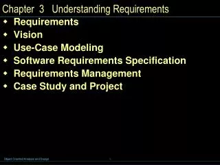
Review – Types of Object-Oriented (OO) Diagrams • Class Diagram • Use Case Diagram • Sequence Diagram • Collaboration Diagram • Statechart Diagram
Object Behavior • Statechart diagram • A diagram showing the life of an object in states and transitions • Based on information from the class diagram and the sequence diagram • How an object performs its actions is called object behavior • Life cycle of an object • Each object is an instance of a class, and comes into existence in some manner • During its existence it is “in” certain states and makes transitions from state to state • These states and the changes an object makes are shown in a statechart diagram
Object States • A state for an object is a condition during its lifetime when it • Satisfies some criteria • Performs some action • Waits for an event • Each unique state has a unique name • E.g. “on”, “working”, “loading equipment” etc. • States are semipermanent conditions • can be interrupted by external events • An object stays in a state until some event causes it to move to another state
Object States (continued) • When an object is in a state it may be • Quiescent (ie. Nothing happening) • Active (ie. Performing some action) • E.g. a computer monitor may be in“off” or “on” states • A state is represented by a rectangle with rounded corners (with the name of the state inside) • Any actions that must be performed during the period of the state are placed below the state name in the rectangle – see next slide
Object States (continued) • In the diagram, the beginning and ending of the statechart was indicated by two darkened circles • In complex systems we need to model situations where there is concurrent states • Concurrency or concurrent states: the condition of being in more than one state at a time within a statechart • Composite state • A high level state that has other states nested within it • Example on next slide – a milling object can be “off” or “on” • If it is on it may have two paths (one for the input bin and one for the machining portion)
Object Transitions • Transition • a component of a statechart that signifies the movement from one state to the next • Destination state • The destination of a transition connected to the arrowhead of the transition symbol • Origin state • The origin for a transition connected to the tail of a transition arrow symbol • Message event • The trigger for a transition consisting of a message that has the properties of an event • Guard-condition • A true/false test to see whether a transition can be taken
Object Transitions (continued) • Transition label (on the arrow in last slide) Transition-name(parameters, …) [guard condition] / action-expression • The transition-name is the name of a message event that causes the object to leave the origin state • The parameter list identifies parameters that the message is to pass to the object (e.g. a customer name) • The guard condition is a test on the transition • The action-expression is the statement on the transition to be performed Eg. OnButtonPushed [Bin not empty AND Safety cover closed] / Status := self-test ()
Object Transitions (continued) • Action-expression • The statement on a transition to describe the action to be performed • Executes when the transition fires • Could be a compound series of steps • Internal transition • A transition within a state that does not remove the object from the state • Entry/ action expression • Do/ action expression • Exit/ action expression
Messages, Transitions, and Actions • Note that sequence diagrams and statecharts are related in that both show messages • Transition names in statechart correspond to message names in the sequence diagram • Objects in statecharts receive and send messages • Messages are normally sent as part of action statement • Represented using dot notation e.g. ControlPanel.UpdateStatus (status)
5. Statechart Diagrams • Next slide shows a statechart diagram for an order object (for the RMO example) • Moves from state of “waiting to be shipped” to “shipped” • A state name should describe a state of being • The object moves from state to state depending on the transitions and messages it gets • Initial transition is called “CreateOrder ()” (almost all statecharts begin with a create message)
Statechart Diagrams (continued) • Completion transition • A transition with no trigger event so that it is taken when the origin state completes its actions • Decision pseudostate • A diamond on a statechart to represent a decision point on a path • Path • A valid sequence of transitions and states through a statechart
Approach to developing a statechart (e.g. for the order object) • All incoming message events are identified across all sequence diagrams involving orders • All output messages are identifed • Once all the messages are identifed, the analyst brainstorms the possible states that might exist for the object • Incoming message events help identify transitions
Concurrent Behavior • Concurrent behavior means an object can do multiple things in parallel • Statechart represents concurrent behavior with multiple paths • Each separate path is called a thread • In the next slide, the solid vertical bar represents a synchronization pseudostate • Denotes a path where the paths split into multiple threads
Statechart Development • Review the class diagram and select classes you will want to make statecharts for • Identify all the input messages across all sequence diagrams for the selected class you are making a statechart for • For each selected class, make a list of all the states you can identify • Build statechart fragments (a portion of the path in a statechart) and sequence the fragments in the correct order
5. Review the paths and look for independent, concurrent paths 6. Expand each transition with the appropriate message event, guard-condition, and action-expression 7. Review and test each statechart • make sure your states are “states of being” • Follow the life cycle of an object from creation to deletion • Be sure your diagram covers all normal and exception conditions • Make sure you’ve included all relevant transitions • Review all possible messages and make sure they are handled