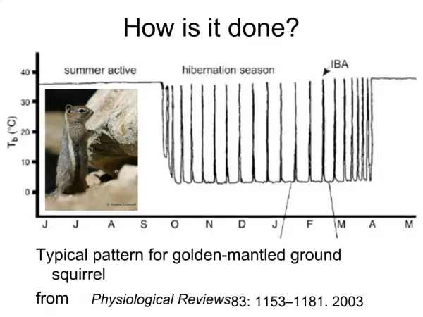
This is how AM modulation is done.
80 likes | 95 Views
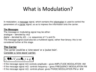
AM modulation essentially consists of the TD multiplication of the modulating signal by a cosine carrier. In the FD, AM modulation effected a frequency shift of the spectrum of a band limited modulating signal from being centered on zero to being centered on the carrier frequency.

This is how AM modulation is done.
E N D
Presentation Transcript
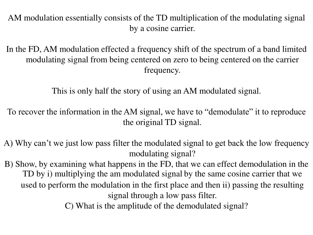
AM modulation essentially consists of the TD multiplication of the modulating signal by a cosine carrier. In the FD, AM modulation effected a frequency shift of the spectrum of a band limited modulating signal from being centered on zero to being centered on the carrier frequency. This is only half the story of using an AM modulated signal. To recover the information in the AM signal, we have to “demodulate” it to reproduce the original TD signal. A) Why can’t we just low pass filter the modulated signal to get back the low frequency modulating signal? B) Show, by examining what happens in the FD, that we can effect demodulation in the TD by i) multiplying the am modulated signalby the same cosine carrier that we used to perform the modulation in the first place and then ii) passing the resulting signal through a low pass filter. C) What is the amplitude of the demodulated signal?
This is how AM modulation is done. In the time domain start with the audio signal, add a DC shift to make it all positive and multiply by the radio frequency carrier to make the modulated signal. Figs from Smith Figure from Smith
This is how AM modulation is done. In the frequency domain this corresponds to the convolution of a shifted delta with the audio spectrum (note there are 2 sidebands, taking into account those funny negative frequencies - they really exist!!). Figure from Smith
We know multiplication in the TD is the same as convolution in the FD. The top plot is the FT of the low-pass filter kernel. The middle plot is the FT of the max non-aliased frequency we multiplied by - it goes into a single point in the FD. The convolution of the two sequences shifts the first (top) to be centered on d in the second (middle). Resulting in the high pass filter kernel ( bottom)! (Notice that we’re making lots of use of the “periodicity” of things in the discrete domain and negative frequencies – for both the LP filter and the delta. They’re REAL!) Figure from Smith
AM modulation is done by multiplying two signals in the TD, which is convolution in the FD -w0 w0 When one of the signals is a single frequency, this gives a delta in the FD. Convolution with a delta just shifts the FD of the second sequence such that it becomes centered on the delta. Notice we are including the negative frequencies in this analysis (it will not work if we dont!). So we have 2 copies of the signal in the FD, each has an amplitude of ½.
a) Why can’t we just low pass filter the modulated signal to get back the low frequency modulating signal? After modulation, there is no signal in the FD inside the LP filter limits, so doing a LP filter does not result in any output.
Now we multiply the AM modulated TD signal (the whole thing in the FD, with both positive and negative frequencies) by the “carrier” frequency again. This causes another shift in the FD. Now we get 4 copies of the spectrum, each at ¼ amplitude, but the two in the middle add together to make one signal of half the amplitude. Finally, now that we have a signal back in the low frequency range, we can low pass filter it.
1 -w0 w0 -2w0 2w0 0