Download
1 / 20
200 likes | 292 Views
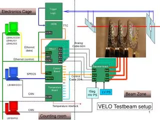
TELL1 VHDL Framework. By Aditya Mittal. Scenario Block Diagram. http://ppewww.physics.gla.ac.uk/~parkes/VeloSoftware/EventModel.jpg. TELL1. Tell1 is the common (used for all sub-detectors) LHCb data acquisition board that operates at 1.11MHz.

E N D
TELL1 VHDL Framework By Aditya Mittal
Scenario Block Diagram http://ppewww.physics.gla.ac.uk/~parkes/VeloSoftware/EventModel.jpg
TELL1 • Tell1 is the common (used for all sub-detectors) LHCb data acquisition board that operates at 1.11MHz http://lphe1dell1.epfl.ch/~ghaefeli/specification_and_documents/TELL1.pdf
CVS • CVS is a concurrent version system • It appends a version number to a file name for each revision of a file stored in a repository • Changes are tracked in a “commit log” file • Basic test side commands include add, remove, commit, and log • Basic release side commands include update and checkout • According to the TELL1 Homepage, they are not using a CVS repository because their HTL Designer (I’m not sure what this is) deletes the repository
TCL (Tool Command Language) Scripts • TCL Scripts make it easy to setup the project or achieve tedious and repetitive tasks • http://tmml.sourceforge.net/doc/tcl/index.html is a reference manual that can be used when writing a TCL Script • The VHDL framework for TELL1 comes with TCL Scripts to make setup easy • The order matters when compiling the TCL Scripts because of the dependencies • QuartusII has a TCL console window under Utilities in which a TCL script can be called and run
Setting up the TELL1 Project for QuartusII • Download the latest .zip file from the website • Extract and save to some location • Open up the environment_setup folder in the hdl folder • Right click and open the set_environment_variables file with a text editor and edit the path to your working directory • Double click and run the setx application and it will set the environment paths • Now open up the preexisting QuartusII file (.qpf) for the particular sub-detector (I used velo_pp_fpga.qpf) and run the TCL scripts in order and the project should all be setup • Do a full compile (it takes a while) and make sure everything works
Directory Structure • The hdl folder has a folder called common_tell1_libraries and another folder called user_tell1_libraries, the user_tell1_libraries are sub-detector specific libraries • There is a processing_doc folder which contains release specific documentation • Other folders like hdl_ini_files or vhdl_export were not very meaningful to me as I was not using Mentor Graphics software for automatic generation of hdl (hardware description language) nor was I trying to add or remove things from the CVS
File Types • We have already talked about tcl scripts • The most important files are vhdl source code files including the entities themselves and their testbenches (the name of the testbench file should be the same as the name of the vhdl entity file with an _tb attached) • .sof and pof files were not meaningful since I did not use Max+PlusII software • Another important file type was .vwf a waveform file which can be used to simulate the inputs and outputs of any entity using the Quartus II Simulator, the .vwf are generated by the QuartusII Waveform Editor
EDA tool Generated Code • A field programmable gate array is a semiconductor device containing programmable logic components and programmable interconnects. The logic components include everything from and, or, not, xor gates to adders, decoders, multiplexers and so on • In an EDA tool a module’s functionality can be defined using VHDL code or schematic diagrams of the logic • Since much of the logic is repeated over and over in places, it is important that it is fully optimized and that the VHDL is written so that the minimum number of components are generated • Often tool generated code is not fully optimized
Inter_position_calc_sum_wsum before and after example • There is one less adder afterwards in the gate level because of the way the line in VHDL code was written
The VHDL modules in the code are built to simulate the desired physics • Things like clusterization, common mode subtraction, pedestal subtraction, weighted sum calculation etc. are all built from these gates and memory read write operations in the VHDL modules • Timing can also be done within the VHDL module based on clocks, which allows us to build state machines • The chapters such as that on clusterization and Input Data Processing for the Velo (Ch3) describe the logic blocks built in the VHDL on TELL1 • The TELL1 Spec Sheet http://lphe1dell1.epfl.ch/~ghaefeli/specification_and_documents/TELL1.pdf has nice block diagrams of the overall structure of TELL1 and the modules inside
VHDL Basics • This is not an attempt to teach VHDL coding, refer to some VHDL Reference like this one for that: http://www.eng.auburn.edu/department/ee/mgc/vhdl.html • But a few concepts should be clear, VHDL supports coding at various hierarchical levels. The levels of abstraction include: Architectural, Algorithmic, RTL, Gate, and Circuit • VHDL also supports both sequential and concurrent statements: All statements within a process are sequential and all processes are concurrent • Entities are the logical building blocks of the system, and components and processes form them • An architecture is an arrangement of these entities connected by ports or buses
Analysis and Synthesis • Upon compilation QuartusII will analyze and synthesize all the entities in relation with each other forming the TELL1 architecture • The Project Navigator on the Side will show all the design units (including entities and their processes and components) in relation to each other • The Node Finder can be used to find all the points at which the various entities are connected to each other
Testbenches • Testbenches are used to test the various entities • It is good practice to write or generate a testbench for each entity in order to ensure proper functionality of the entity and the system • A good testbench should cover all the corner cases that can arise in the code • This is part of functional verification
The TELL1 Code • The VHDL code is all at the RTL level, Gate Level Optimizations can be made but would be rather tedious for such a large project • The C code is all at the Algorithmic level • It is well structured and easy to navigate • Throughout the project, a few testbenches exist here and there for higher level entities but not enough, therefore, it would be hard to detect bugs • It is a large project and adding testbenches will make it larger still
Wavefile Simulation • There are two types of simulations that can be done functional and timing with the QuartusII simulator • The functional simulator lets us view a bunch of signals at any 1 point in time • The timing simulator lets us view 1 signal at many points in time
Behavioral Simulation • Using EDA tool such as Scirocco from Synopsis one can do Behavioral Simulation which allows us to view the change in many signals and vectors in time as dictated by a testbench • In order to use Scirocco first the vhdl entity file and its testbench must be compiled using the “vhdlan” command in a qsh shell running synopsis • Next, one needs to compile the top level configuration of the entity using the “scs” command • Finally, launch Simulator VirSim Gui using “scirocco &” and after putting in “./scsim” into the main window launch scirocco by pressing ok • Open up the Hierarchy window and run for 150ns or so after selecting the waveform
Verification Steps after Simulation • After writing the code it needs to be verified before release for implementation • Simulation using test benches and test vectors is the first step in functional verification • Equivalence checking and formal verification are next steps, for TELL1 VHDL code this might be easier because the functionality of the modules can be checked against the C code • Mixed Signal Analysis etc. may also be performed at a later stage in Verification