Download
1 / 22
220 likes | 563 Views
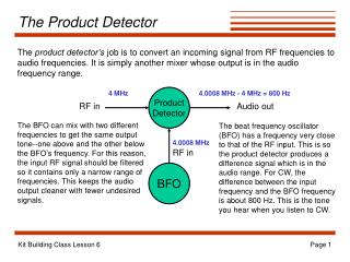
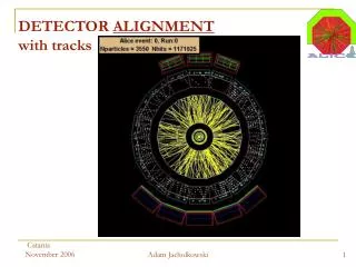
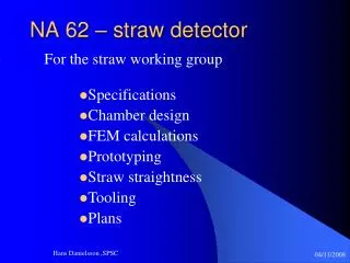
NA 62 – straw detector. For the straw working group. Specifications Chamber design FEM calculations Prototyping Straw straightness Tooling Plans. Straw tracker layout. 448x16 = 7168 straws Operate in vacuum 2.1m long D i =9.8mm Precise tracking (<120 μm) Straw rate: up to 0.5 MHz

E N D
NA 62 – straw detector For the straw working group • Specifications • Chamber design • FEM calculations • Prototyping • Straw straightness • Tooling • Plans Hans Danielsson ,SPSC
Straw tracker layout • 448x16 = 7168 straws • Operate in vacuum 2.1m long Di =9.8mm • Precise tracking (<120 μm) • Straw rate: up to 0.5 MHz • Non-flammable gas mixture • CO2 (80%)+ CF4 (16%) + Isobutene (6%) • (Test beam 2008) • For more parameters see files in EDMS: • https://edms.cern.ch/document/837445/1 • https://edms.cern.ch/document/908415/1 4 chambers 4 views in each chamber 448 (4x112) straws in each view 448 (4x112) straws in each view Hans Danielsson ,SPSC 04/11/2008
Chamber design O-rings Ring for sealing Hans Danielsson ,SPSC 04/11/2008
FEM calculations of the chamber Hans Danielsson ,SPSC
FEM calculations of the chamber Stress levels • The model contains all the loading details: Pressure difference, pretension, fixation points to the vacuum tube etc. • We have a model to study global deformations and details e.g. stress concentration around the holes. • We are working on a model to study the deformation of individual straws. • 25 mm thickness looks ok • Basis for price enquiry Hans Danielsson ,SPSC
Prototypes of the gas manifold, straw connectivity and web • The design of the web(16 channels) is finished and a prototype is launched in the. 4– 6 weeks for production • Questions that will be addressed are: • Type of glue • Gluing procedure • Tooling and access • Leak tightness • Electrical connection to the straws (web) Hans Danielsson ,SPSC
A set-up to measure the straw tension This method was developed to study the straw straightness under tension and pressure An IR light sensitive sensor gives a voltage proportional to the reflected IR light from the LED Tension wf2where w is the weight per unit length and f the frequency To be used in the QC of the chamber production Hans Danielsson ,SPSC
Deformation of the straw as a function of pressure for different pre-tension Negative Poisson’s ratio! which results in a loss of tension when pressurized x=-y Hans Danielsson ,SPSC
Results of the mechanical test • Negative Poisson's ratio! • The loss of tension with 1 bar is between 300g-400g • 800 g of final straw pre-tension should be enough (with some safety) • 1 kg is 1.2 mm deflection for a 1.85 m straw ( 1.75 mm for a 2.1m straw). • We need 2 supports for the straws and possibly wire guides • It is important to measure the tension after insertion • We need experimental results of the long time mechanical behavior of the straws under realistic conditions (from 2007) Hans Danielsson ,SPSC
Straw straightness with 50 mm precision LabVIEW program panel of edge detection Edge parameter line profile To be used in the QC of the chamber production Hans Danielsson ,SPSC
Beam test 2008 • The goal was to compare two candidates for the FE chips and operate the chamber with the new non-flammable gas mixture • Same straw prototype as in 2007 was equipped with two types of FE: CARIAOCA and ASDQ. Test boards were prepared in August at CERN, for these two chips • The straw prototype was ready to take data as planned on the 2:nd of October. However, the beam was stopped on the 6:th of October. • Nevertheless, we managed to take six points with muons (different HV and threshold): HV (kV): 2.4 , 2.5 , 2.6 ( at two different thresholds), 2.7 • The off-line analysis is going on. • Since then, we have learned that: • Only a maximum of 900 chips (7200 channels) are available of the ASDQ chip (no spare!) CARIOCA is the baseline for our FE Hans Danielsson ,SPSC
Example of study on the FE FEE sensitivity measurements in June by injection known charge Qin [fC] into various points 3 1 2 Straw as a coaxial line with losses R1=Rc R loss CARIOCA R2=Rc DET gnd (cathode) FEE gnd Signal – current source 1 Sensitivity =16mV/fC (100%) - CARIOCA 2 Sensitivity = 8.3mV/fC (50%) – reduction due to current division 3 Sensitivity = 4.5mV/fC (~30%) – with termination on far-end (max R loss) 3 Sensitivity = 11.2mV/fC (70%) at open far-end Hans Danielsson ,SPSC 04/11/2008
Future Plans • Terminate the detailed study on the straw material and its mechanics • Detailed FEM analysis of the structure and the straw • Finalize layout of the mechanical structure • Plan and build a new sector prototype: • Verify mechanical support of the straws (and wire). Measure final straw deformation and wire off-set • New straw layout • New connectivity • Final electronics CARIOCA • Build a full-scale engineering prototype • Aging component validation Hans Danielsson ,SPSC
FEM calculations of the chamber Hans Danielsson ,SPSC
Chamber design (detail) Hans Danielsson ,SPSC
Two wire guides in the straw do limit wire off-set 0.23 g 0.23 g • Yes, it is possible in terms of added wire sag 1/3 1/3 d = + 0.16mm We have to see if this is necessary. It complicates the wire stringing , but reduces significantly the risk of wire-off -set in case of bent straws Hans Danielsson ,SPSC
Theoretical Hans Danielsson ,SPSC
Test beam 2008 Phi=+7.5 degree • Modification of the geometry compared to 2007: • Rotating of the prototype to avoid that the wires line up with the beam axis Hans Danielsson ,SPSC
Assembly of web connection and gas manifolds Hans Danielsson ,SPSC