Error Detection
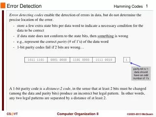
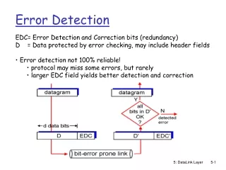
Error Detection. EDC= Error Detection and Correction bits (redundancy) D = Data protected by error checking, may include header fields Error detection not 100% reliable! protocol may miss some errors, but rarely larger EDC field yields better detection and correction. Parity Checking.

Error Detection
E N D
Presentation Transcript
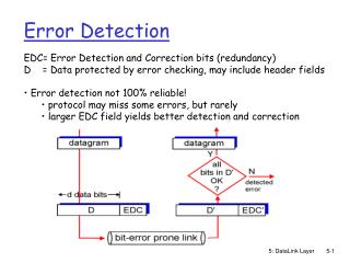
Error Detection • EDC= Error Detection and Correction bits (redundancy) • D = Data protected by error checking, may include header fields • Error detection not 100% reliable! • protocol may miss some errors, but rarely • larger EDC field yields better detection and correction 5: DataLink Layer
Parity Checking Two Dimensional Bit Parity: Detect and correct single bit errors Single Bit Parity: Detect single bit errors 0 0 5: DataLink Layer
Sender: treat segment contents as sequence of 16-bit integers checksum: addition (1’s complement sum) of segment contents sender puts checksum value into UDP checksum field Receiver: compute checksum of received segment check if computed checksum equals checksum field value: NO - error detected YES - no error detected. But maybe errors nonetheless? More later …. Internet checksum Goal: detect “errors” (e.g., flipped bits) in transmitted segment (note: used at transport layer only) 5: DataLink Layer
Checksumming: Cyclic Redundancy Check • view data bits, D, as a binary number • choose r+1 bit pattern (generator), G • goal: choose r CRC bits, R, such that • <D,R> exactly divisible by G (modulo 2) • receiver knows G, divides <D,R> by G. If non-zero remainder: error detected! • can detect all burst errors less than r+1 bits • widely used in practice (ATM, HDCL) 5: DataLink Layer
CRC Example Want: D.2r XOR R = nG equivalently: D.2r = nG XOR R equivalently: if we divide D.2r by G, want remainder R D.2r G R = remainder[ ] 5: DataLink Layer
Code Division Multiple Access (CDMA) • used in several wireless broadcast channels (cellular, satellite, etc) standards • unique “code” assigned to each user; i.e., code set partitioning • all users share same frequency, but each user has own “chipping” sequence (i.e., code) to encode data • encoded signal = (original data) X (chipping sequence) • decoding: inner-product of encoded signal and chipping sequence • allows multiple users to “coexist” and transmit simultaneously with minimal interference (if codes are “orthogonal”) 5: DataLink Layer
d0 = 1 1 1 1 1 1 1 d1 = -1 1 1 1 1 1 1 1 1 1 1 1 1 1 1 1 1 1 1 1 1 1 1 1 1 1 1 - - - - - - - - - - - - - - - - - - - - - - - - - - - - - - - - 1 1 1 1 1 1 1 1 1 1 1 1 1 1 1 1 1 1 1 1 1 1 1 1 1 1 1 1 1 1 1 1 M Di = SZi,m.cm m=1 M d0 = 1 d1 = -1 CDMA Encode/Decode channel output Zi,m Zi,m= di.cm data bits sender slot 0 channel output slot 1 channel output code slot 1 slot 0 received input slot 0 channel output slot 1 channel output code receiver slot 1 slot 0 5: DataLink Layer
CDMA: two-sender interference 5: DataLink Layer