Download
1 / 76
770 likes | 1k Views
Physical Layer Issues - Transmission Media and Network Cabling. Hitesh lad. What is Cable? Transmission Media. Transmission medium is the physical path between the transmitter and receiver.

E N D
Physical Layer Issues - Transmission Media and Network Cabling Hitesh lad
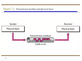
What is Cable? Transmission Media • Transmission medium is the physical path between the transmitter and receiver. • It is the Transmission medium through which information usually moves from one network device to another. • In some cases, a network will utilize only one type of cable, other networks will use a variety of cable types. • Understanding the characteristics of different types of transmission media and how they relate to other aspects of a network is necessary for the development of a successful network.
Factors to Select Transmission Media • Data Rate and Bandwidth (BPS and Hz) • Distance and Attenuation (meters, dB/km) • Interference Characteristics • Number of receivers (broadcast vs. point to point) • Cost - Remember cabling is a long term investment!
Transmission Impairments • Impairments exist in all forms of data transmission media • Analog signal impairments result in random modifications that impair signal quality • Digital signal impairments result in bit errors (1s and 0s transposed)
Types of Media • Two major classes • Conducted or guided media • use a conductor such as a wire or a fiber optic cable to move the signal from sender to receiver. • Energy is confined to the medium and guided by it • Wireless or unguided media • use radio waves of different frequencies and do not need a wire or cable conductor to transmit signals • Energy spreads out and is not confined
Media Sub-types • Guided Media • Unshielded Twisted Pair (UTP) Cable • Shielded Twisted Pair (STP) Cable • Coaxial Cable • Fiber Optic Cable • Unguided Media • Terrestrial microwave transmission • Satellite transmission • Broadcast radio • Infrared
Twisted Pair Wires • Consists of two insulated copper wires arranged in a regular spiral pattern to minimize the electromagnetic interference between adjacent pairs • Often used at customer facilities and also over distances to carry voice as well as data communications • Low frequency transmission medium • Two varieties • STP (shielded twisted pair) • the pair is wrapped with metallic foil or braid to insulate the pair from electromagnetic interference • UTP (unshielded twisted pair) • each wire is insulated with plastic wrap, but the pair is encased in an outer covering
Twisted Pair One difference between the different categories of UTP is the tightness of the twisting of the copper pairs. The tighter the twisting, the higher the supported transmission rate and the greater the cost per foot. Each pair is twisted with a different number of twists per inch to help eliminate interference from adjacent pairs and other electrical devices.
Categories of Unshielded Twisted Pair The EIA/TIA (Electronic Industry Association/Telecommunication Industry Association) has established standards of UTP and rated five categories of wire. • TypeUse • Category 1 Voice Only (Telephone Wire) • Category 2 Data to 4 Mbps (LocalTalk) • Category 3 Data to 10 Mbps (Ethernet) • Category 4 Data to 20 Mbps (16 Mbps Token Ring) • Category 5 Data to 100 Mbps (Fast Ethernet) • Category 5e Data to 1000 Mbps (Gigabit Ethernet) • Category 6 Data to 1000 Mbps (Gigabit Ethernet) • Category 7 ?
Benefits of UTP • Inexpensive and readily available • Flexible and light weight • Easy to work with and install • Disadvantages of UTP • Susceptibility to interference and noise • Attenuation problem • For analog, repeaters needed every 5-6km • For digital, repeaters needed every 2-3km • Relatively low bandwidth (3000Hz)
Twisted Pair - Applications • Telephone network • Between house and local exchange (subscriber loop/local loop) • Within buildings • To private branch exchange (PBX) • For local area networks (LAN) • 10Mbps or 100Mbps or 1000 Mbps
Unshielded Twisted Pair Connector • The standard connector for unshielded twisted pair cabling is an RJ-45 connector. This is a plastic connector that looks like a large telephone-style connector (See figure). • A slot allows the RJ-45 to be inserted only one way. RJ stands for Registered Jack, implying that the connector follows a standard borrowed from the telephone industry. This standard designates which wire goes with each pin inside the connector.
Shielded Twisted Pair (STP) Cable • A disadvantage of UTP is that it may be susceptible to radio and electrical frequency interference (RFI, EFI). • Shielded twisted pair (STP) is suitable for environments with electrical interference; however, the extra shielding can make the cables quite bulky. • Shielded twisted pair is often used on networks using Token Ring topology. • More expensive, harder to work with.
Coaxial Cable • Coaxial cabling has a single copper conductor at its center. A plastic layer provides insulation between the center conductor and a braided metal shield (See figure). The metal shield helps to block any outside interference from fluorescent lights, motors, and other computers. Both conductors share a common center axis, hence the term “co-axial”
Coax Layers outer jacket (polyethylene) shield(braided wire) insulating material copper or aluminum conductor
Pros and Cons • Coax Advantages • Higher bandwidth • 400 to 600MHz • up to 10,800 voice conversations • Can be tapped easily (pros and cons) • Much less susceptible to interference than twisted pair • Greater cable lengths between network devices than twisted pair cable. • Coax Disadvantages • High attenuation rate makes it expensive over long distance • Bulky - coaxial cabling is difficult to install
Coaxial Cable Applications • Most versatile medium • Television distribution • Ariel to TV • Cable TV • Long distance telephone transmission • Can carry 10,000 voice calls simultaneously • Being replaced by fiber optic • Short distance computer systems links • Local area networks
Types of Coaxial Cable • Thin Coax • Thin coaxial cable is also referred to as thinnet. Thin coaxial cable is popular in linear bus networks. • Thick Coax • Thick coaxial cable is also referred to as thicknet. • Thick coaxial cable has an extra protective plastic cover that helps keep moisture away from the center conductor. This makes thick coaxial a great choice when running longer lengths in a linear bus network. • One disadvantage of thick coaxial is that it does not bend easily and is difficult to install.
Coaxial Cable Connectors • The most common type of connector used with coaxial cables is the Bayone-Neill-Concelman (BNC) connector (See figure). Different types of adapters are available for BNC connectors, including a T-connector, barrel connector, and terminator. Connectors on the cable are the weakest points in any network. To help avoid problems with your network, always use the BNC connectors that crimp, rather than screw, onto the cable.
Fiber Optic Cable • Relatively new transmission medium used by telephone companies in place of long-distance trunk lines • Also used by private companies in implementing local data communications networks • Require a light source with injection laser diode (ILD) or light-emitting diodes (LED)
Fiber Optic Cable • Fiber optic cabling consists of a center glass core surrounded by several layers of protective materials. • It transmits light rather than electronic signals, eliminating the problem of electrical interference. This makes it ideal for certain environments that contain a large amount of electrical interference. • It has also made it the standard for connecting networks between buildings, due to its immunity to the effects of moisture and lighting.
plastic jacket glass or plastic cladding fiber core Fiber Optic Layers • consists of three concentric sections
Facts About Fiber Optic Cables • Facts about fiber optic cables: • Outer insulating jacket is made of Teflon or PVC. • Kevlar fiber helps to strengthen the cable and prevent breakage. • A plastic coating is used to cushion the fiber center. • Center (core) is made of glass or plastic fibers.
Fiber Optic Cable • Fiber optic cable has the ability to transmit signals over much longer distances than coaxial and twisted pair. • It also has the capability to carry information at vastly greater speeds. This capacity broadens communication possibilities to include services such as video conferencing and interactive services. • The cost of fiber optic cabling is comparable to copper cabling; however, it is more difficult to install and modify.
Optical Fiber - Transmission Characteristics • Act as wave guide for 1014 to 1015 Hz • Portions of infrared and visible spectrum • Light Emitting Diode (LED) • Cheaper • Wider operating temp range • Last longer • Injection Laser Diode (ILD) • More efficient • Greater data rate • Wavelength Division Multiplexing
Fiber Optic Types • Multimode step-index fiber • the reflective walls of the fiber move the light pulses to the receiver • Multimode graded-index fiber • acts to refract the light toward the center of the fiber by variations in the density • Single mode fiber • the light is guided down the center of an extremely narrow core
Fiber Optic Signals fiber optic multimode step-index fiber optic multimode graded-index fiber optic single mode
Pros and Cons • Fiber Optic Advantages • Greater capacity - data rates of hundreds of Gbps • Smaller size and lighter weight • Lower attenuation • Electromagnetic isolation - immunity to environmental interference and highly secure due to tap difficulty and lack of signal radiation • Greater repeater spacing - 10s of km at least • Fiber Optic Disadvantages • Expensive over short distance • Requires highly skilled installers • Adding additional nodes is difficult
Optical Fiber - Applications • Long-haul trunks • Metropolitan trunks • Rural exchange trunks • Subscriber loops (FTTH, FTTC) • LANs (generally backbone connections)
Fiber Optic Connector • The most common connector used with fiber optic cable is an ST connector. It is barrel shaped, similar to a BNC connector. A newer connector, the SC, is becoming more popular. It has a squared face and is easier to connect in a confined space.
100 22-gauge Twisted Pair 3/8” Coaxial Cable dB/km 10 1 Optical Fiber 0.1 1 kHz 1 MHz 1 GHz 1 THz 1000 THz Frequency Comparison of the Three Guided Media Types
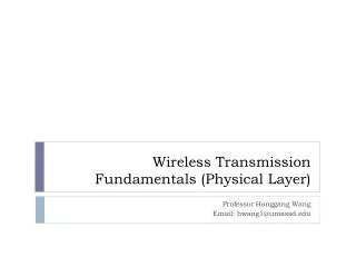
Wireless (Unguided Media) • Transmission • Transmission and reception are achieved by means of an antenna • Directional • transmitting antenna puts out focused beam • transmitter and receiver must be aligned • Omnidirectional • signal spreads out in all directions • can be received by many antennas
Wireless (Unguided Media) Frequencies • Three general ranges of frequencies • 30MHz to 1GHz • Broadcast radio • Omnidirectional • 2GHz to 40GHz microwave frequencies • Microwave • Highly directional • Point to point • Satellite • 3 x 10¹¹ to 2 x 10¹⁴ • Infrared
Terrestrial Microwave Transmission • Uses the radio frequency spectrum, commonly from 2 to 40 GHz • Transmitter is a parabolic dish, mounted as high as possible • Used by common carriers as well as by private networks • Requires unobstructed line of sight between source and receiver • Curvature of the earth requires stations (called repeaters) to be ~30 miles apart
Terrestrial Microwave Transmission • Distance between antennas: • d = 7.14 (Kh)1/2 , d = distance in km, h is antenna height in meters, K = constant = 4/3
Terrestrial Microwave Applications • Long-haul telecommunications service for both voice and television transmission • Short point-to-point links between buildings for closed-circuit TV or a data link between LANs
Pros and Cons • Microwave Transmission Advantages • No cabling needed between sites • Wide bandwidth • Multi-channel transmissions • Used for long haul or high capacity short haul • Requires fewer amplifiers and repeaters • Microwave Transmission Disadvantages • Line of sight requirement • Expensive towers and repeaters • Subject to interference such as passing airplanes and rain • Frequency bands are regulated
Satellite Microwave Transmission • Satellite is a microwave relay station in space • Can relay signals over long distances • Geostationary satellites • remain above the equator at a height of 22,300 miles (geosynchronous orbit) • travel around the earth in exactly the time the earth takes to rotate • Earth stations communicate by sending signals to the satellite on an uplink • The satellite then repeats those signals on a downlink • The broadcast nature of the downlink makes it attractive for services such as the distribution of television programming
Satellite Transmission Process satellite transponder dish dish 22,300 miles uplink station downlink station