Download
1 / 27
270 likes | 368 Views
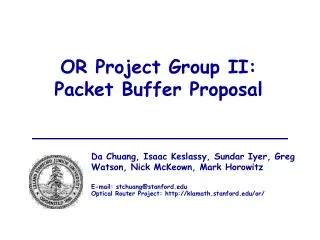
OR Project Group II: Packet Buffer Proposal. Da Chuang, Isaac Keslassy, Sundar Iyer, Greg Watson, Nick McKeown, Mark Horowitz E-mail: stchuang@stanford.edu Optical Router Project: http://klamath.stanford.edu/or/. Outline. Load-Balancing Background Mis-sequencing Problem

E N D
OR Project Group II: Packet Buffer Proposal Da Chuang, Isaac Keslassy, Sundar Iyer, Greg Watson, Nick McKeown, Mark Horowitz E-mail: stchuang@stanford.edu Optical Router Project: http://klamath.stanford.edu/or/
Outline • Load-Balancing Background • Mis-sequencing Problem • Datapath Architecture • First stage - Segmentation • Second stage – Main Buffering • Third stage - Reassembly
100Tb/s router Switch Fabric Electronic Linecard #1 Electronic Linecard #625 160 Gb/s 160 Gb/s • Line termination • IP packet processing • Packet buffering • Line termination • IP packet processing • Packet buffering 160Gb/s 160Gb/s Arbitration Request Grant (100Tb/s = 625 * 160Gb/s)
1 2 1 2 1 1 1 N N N Load-Balanced Switch External Inputs Internal Inputs External Outputs Load-balancing cyclic shift Switching cyclic shift
VOQs 1 2 N 160 Gbps Linecard R Fixed-size Packets R Lookup/Processing Segmentation Load-balancing R Input Block R Output Block Intermediate Input Block Switching R R Reassembly
Outline • Load-Balancing Background • Mis-sequencing Problem • Datapath Architecture • First stage - Segmentation • Second stage – Main Buffering • Third stage - Reassembly
1 2 1 2 1 1 1 N N N Problem: Unbounded Mis-sequencing External Inputs Internal Inputs External Outputs Spanning Set of Permutations Spanning Set of Permutations
N 1 N 1 1 1 N N Preventing Mis-sequencing Middle stage 1 1 1 N N N • Uniform Frame Spreading: • Group cells by frames of N cells each (frame building) • Spread each frame across all middle linecards • Each middle stage receives the same type of packets => has the same queue occupancy state
Outline • Load-Balancing Background • Missequencing Problem • Datapath Architecture • First stage - Segmentation • Second stage – Main Buffering • Third stage - Reassembly
1st stage 2nd stage 3rd stage R/N 1 1 1 R R R R R R 2 2 2 N N N Segmentation/ Frame Building Reassembly Main Buffering Three stages on a linecard
Technology Assumptions in 2005 • DRAM Technology • Access Time ~ 40 ns • Size ~ 1 Gbits • Memory Bandwidth ~ 16 Gbps (16 data pins) • On-chip SRAM Technology • Access Time ~ 2.5 ns • Size ~ 64 Mbits • Serial Link Technology • Bandwidth ~ 10 Gb/s • >100 serial links per chip
1 1 1 2 2 2 N N N First Stage 16-bytes 16-bytes 0-15 0-15 R/8 R/8 variable-size packets 16-31 16-31 128-byte cells 1 R/8 R/8 2 R N 108-127 Segmentation 108-127 R/8 R/8 Frame Building
Segmentation Chip (1st stage) 16-bytes 0-15 R/8 variable-size packets 128-byte cells 16-31 1 2 R/8 R N 108-127 Segmentation R/8 • Incoming: 16x10 Gb/s • Outgoing: 8x2x10 Gb/s • On-chip Memory: N x 1500 bytes = 7.2 Mbits 3.2ns SRAM
1 2 N Frame Building Chip (1st stage) 16-bytes 16-bytes 0-15 0-15 R/8 R/8 Frame Building • Incoming: 2x10 Gb/s • Outgoing: 2x10 Gb/s • On-chip Memory: N^2 x 16 bytes = 48 Mbits 3.2ns SRAM
Three stages on a linecard 1st stage 2nd stage 3rd stage R/N 1 1 1 R R R R R R 2 2 2 N N N Segmentation/ Frame Building Reassembly Main Buffering
Write Rate, R One 128B packet every 6.4ns Read Rate, R One 128B packet every 6.4ns Packet Buffering Problem Packet buffers for a 160Gb/s router linecard 40Gbits Buffer Memory Buffer Manager
Memory Technology • Use SRAM? +Fast enough random access time, but • Too low density to store 40Gbits of data. • Use DRAM? +High density means we can store data, but • Can’t meet random access time.
Large DRAM memory holds the body of FIFOs 54 53 52 51 50 10 9 8 7 6 5 1 95 94 93 92 91 90 89 88 87 86 15 14 13 12 11 10 9 8 7 6 2 86 85 84 83 82 11 10 9 8 7 DRAM Q Reading b bytes Writing b bytes 1 1 4 3 1 2 Arriving Departing 55 60 59 58 57 56 2 Packets Packets 2 1 2 4 3 5 97 96 R R Q Q 6 5 4 3 2 1 SRAM 87 88 91 90 89 Arbiter or Scheduler Small head SRAM Small tail SRAM Requests cache for FIFO heads cache for FIFO tails Hybrid Memory Hierarchy
SRAM/DRAM results • How much SRAM buffering, given: • DRAM Trc = 40ns • Write and read a 128-byte cell every 6.4ns • Let Q = 625, b = 2*40ns/6.4ns = 12.5 • Two Options [Iyer] • Zero Latency Qb[2+lnQ] = 61k cells = 66 Mbits • Some Latency Q(b-1) = 7.5k cells = 7.5 Mbits
Outline • Load-Balancing Background • Missequencing Problem • Datapath Architecture • First stage - Segmentation • Second stage – Main Buffering • Third stage - Reassembly
Problem Statement 40 Gb DRAM 160 Gb/s 160 Gb/s Write Rate, R Read Rate, R Queue Manager 160 Gb/s 160 Gb/s One 128B cell every 6.4ns One 128B cell every 6.4ns
R/N R/N R/N 1 1 1 2 2 2 N N N Second Stage 16-bytes 16-bytes 0-15 0-15 R/8 R/8 16-31 16-31 R/8 R/8 108-127 108-127 R/8 R/8 Main Buffering
R/N 1 2 N Queue Manager Chip (2nd stage) 5 x 1Gb DRAM R/4 R/4 16-bytes 16-bytes 0-15 0-15 R/8 R/8 Main Buffering • Incoming: 2x10 Gb/s • Outgoing: 2x10 Gb/s • 35 pins/DRAM x 5 DRAMs = 175 pins • SRAM/DRAM Memory: Q(b-1) = 2.8 Mbits 3.2ns SRAM • SRAM linked list = 1 Mbit 3.2ns SRAM
Outline • Load-Balancing Background • Missequencing Problem • Datapath Architecture • First stage - Segmentation • Second stage – Main Buffering • Third stage - Reassembly
Three stages on a linecard 1st stage 2nd stage 3rd stage R/N 1 1 1 R R R R R R 2 2 2 N N N Segmentation/ Frame Building Reassembly Main Buffering
Third stage 16-bytes 0-15 variable-size packets 16-31 R/8 1 2 R/8 R N 108-127 Reassembly R/8 • Incoming: 8x2x10 Gb/s • Outgoing: 16x10 Gb/s • On-chip Memory: N x 1500 bytes = 7.2 Mbits 3.2ns SRAM
Linecard Datapath Requirements • 1st stage • 1 segmentation chip • 8 frame building chips • 2nd stage • 8 queue manager chips • 40 1 Gb DRAMs • 3rd stage • 1 reassembly chip • Total chip count • 18 ASIC chips • 40 1 Gb DRAMs