Download
1 / 22
230 likes | 255 Views
Study on dynamic response evaluation of Boeing 737 fuselage section with overhead bins in a vertical drop test. Using finite element modeling and crash simulation to correlate analytical and experimental data for improved accuracy.

E N D
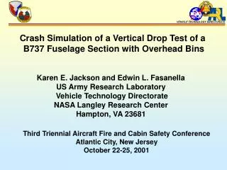
VEHICLE TECHNOLOGY DIRECTORATE Crash Simulation of a Vertical Drop Test of a B737 Fuselage Section with Overhead Bins Karen E. Jackson and Edwin L. Fasanella US Army Research Laboratory Vehicle Technology Directorate NASA Langley Research Center Hampton, VA 23681 Third Triennial Aircraft Fire and Cabin Safety Conference Atlantic City, New Jersey October 22-25, 2001
VEHICLE TECHNOLOGY DIRECTORATE Introduction and Background Information • In November of 2000, the FAA performed a 30-ft/s vertical • drop test of a 10-ft. long fuselage section of a Boeing 737 • (B737) transport aircraft • The fuselage section was outfitted with two different • commercial overhead stowage bins and luggage • The objective of the test was to evaluate the dynamic • response of the overhead bins in a narrow-body • transport fuselage section subjected to a severe, but • survivable, impact event • This test also provided a unique opportunity to evaluate • the capabilities of computational tools for crash • simulation
VEHICLE TECHNOLOGY DIRECTORATE Objectives • To develop a finite element model of the fuselage • section suitable for execution in a crash simulation • Perform a crash simulation using the nonlinear, • explicit transient dynamic code, MSC.Dytran, and • generate pre-test predictions of fuselage and • overhead bin dynamic responses • Validate the model through extensive analytical and • experimental correlation • Assess simulation accuracy and suggest changes • to the model for improved correlation
VEHICLE TECHNOLOGY DIRECTORATE Vertical Drop Test of a B737 Fuselage Section • 10-ft. long section of a B737-100 • transport aircraft from FS 380 to • FS 500, weighing 1, 360-lbs. • Six triple-occupant passenger seats • with test dummies and mannequins • 3,229-lbs. of luggage • Two different commercial overhead • stowage bins loaded with wood • 14-ft. drop test onto wooden platform • for 30-ft/s vertical velocity • ≈140 channels of data collected • at 10,000 samples per second Pre-test photograph
VEHICLE TECHNOLOGY DIRECTORATE Vertical Drop Test of a B737 Fuselage Section Heath Tecna Overhead Bin Forward FS 400 FS 420 FS 440 FS 460 FS 480
VEHICLE TECHNOLOGY DIRECTORATE FS 480 FS 460 FS 440 FS 420 FS 400 Vertical Drop Test of a B737 Fuselage Section Hitco Overhead Bin Forward
VEHICLE TECHNOLOGY DIRECTORATE Seat rails Front Seats Right Left Rear Asymmetry in the Test Article Floor Plan View Schematic Photograph of the Cargo Door
VEHICLE TECHNOLOGY DIRECTORATE Vertical Drop Test of a B737 Fuselage Section Post-test Photographs Right-side seat failure Asymmetric deformation of the lower fuselage
Crash Simulation of the Vertical DropTest of the B737 Fuselage Section VEHICLE TECHNOLOGY DIRECTORATE MSC.Dytran Model Development • Model geometry was developed • from hand measurements, i.e. • no engineering drawings available • Model contains 9, 759 nodes • and 13,638 elements, including • 9, 322 shell and 4, 316 beam • elements • Seats, dummies, cameras, • luggage, and plywood in bins • modeled using concentrated • masses • Material properties were estimated • using engineering judgement Front view of model
Crash Simulation of the Vertical DropTest of the B737 Fuselage Section VEHICLE TECHNOLOGY DIRECTORATE MSC.Dytran Model of the Heath Tecna Bin Front view Three-quarter view Side view
Crash Simulation of the Vertical DropTest of the B737 Fuselage Section VEHICLE TECHNOLOGY DIRECTORATE MSC.Dytran Model of the Hitco Bin Front view Three-quarter view Side view
Crash Simulation of the Vertical DropTest of the B737 Fuselage Section VEHICLE TECHNOLOGY DIRECTORATE MSC.Dytran Model Execution • Rigid impact surface was added • to represent the wooden platform • 3 master-surface to slave-node • contact surfaces were defined • between: • - the impact surface and lower • fuselage structure • - the Heath Tecna bin and the • upper fuselage structure • - the Hitco bin and the upper • fuselage structure • The model was executed for 0.2 • seconds of simulation time, requiring • 36 hours of CPU on a Sun Ultra • Enterprise 450 workstation computer Three-quarter view of model
VEHICLE TECHNOLOGY DIRECTORATE Analytical and Experimental Correlation Vertical Acceleration Responses of the Left-Side Inner and Outer Seat Track at FS 484 Acceleration, g Acceleration, g Time, s Time, s Left outer seat track Left inner seat track
VEHICLE TECHNOLOGY DIRECTORATE Analytical and Experimental Correlation Vertical Acceleration Responses of the Right-Side Inner and Outer Seat Track at FS 484 Acceleration, g Acceleration, g Time, s Time, s Right outer seat track Right inner seat track
VEHICLE TECHNOLOGY DIRECTORATE Analytical and Experimental Correlation Vertical Velocity Responses of the Left- and Right-Side Outer Seat Track at FS 418 Velocity, ft/s Velocity, ft/s Time, s Time, s Left outer seat track Right outer seat track
VEHICLE TECHNOLOGY DIRECTORATE Analytical and Experimental Correlation Vertical Acceleration Responses of the Left- and Right-Side Lower Side Wall at FS 480 Acceleration, g Acceleration, g Time, s Time, s Right-side lower side wall Left-side lower side wall
VEHICLE TECHNOLOGY DIRECTORATE Axial Force Responses of the Vertical Support Rods HT-1 and HT-3 of the Heath Tecna Bin Measured tensile failure load = 1,656 lbs. Axial Force, lbs. Axial Force, lbs. Time, s Time, s Rear support rod, HT-3 Forward support rod, HT-1
VEHICLE TECHNOLOGY DIRECTORATE Axial Force Responses of the .616-in. Diameter Support Rods H-1 and H- of the Hitco Bin Measured tensile failure load = 5,350 lbs. Axial Force, lbs. Axial Force, lbs. Time, s Time, s Support rod, H-2 Support rod, H-1
VEHICLE TECHNOLOGY DIRECTORATE Analytical and Experimental Correlation Predicted Structural Deformation Time = 0.0 s Time = 0.06 s Time = 0.09 s Time = 0.18 s Time = 0.12 s Time = 0.15 s
VEHICLE TECHNOLOGY DIRECTORATE Concluding Remarks • A finite element model of the B737 fuselage section with • overhead bins and luggage was developed and pre-test • predictions of fuselage and bin responses were generated • The model was generated from hand measurements of • fuselage geometry (no engineering drawings were available) • Predicted floor-level acceleration responses compared • favorably with experimental data with peak acceleration • values with ±5-g • Integrated velocity comparisons indicate that the model is • too stiff and removes velocity more quickly that the test • Deformed plots of the model indicate excessive deformation • of the lower fuselage structure into the cargo hold
VEHICLE TECHNOLOGY DIRECTORATE Ongoing Research Suggested Model Improvements • Incorporate platform model • Model luggage physically • using solid elements • Add rotation springs at joints • between bin linkages • Modify material properties • Rediscretize model in certain • regions • Examine the effect of the • contact penalty factor Fuselage Model with Platform Fuselage Model with Luggage
VEHICLE TECHNOLOGY DIRECTORATE Acknowledgements • This research was performed under an Inter Agency • Agreement DTFA03-98-X-90031, established in 1998, • between the US Army Research Laboratory, Vehicle • Technology Directorate and the FAA William J. Hughes • Technical Center. • The technical support and contributions provided by • Gary Frings, Tong Vu, and Allan Abramowitz of the • FAA are gratefully acknowledged.