Download
1 / 33
330 likes | 347 Views
Detailed overview of FEL guns at Jefferson Lab, focusing on high voltage performance, photocathode advancements, and next-gen design concepts. Includes maintenance procedures, vacuum environment, and test stand development for electron beam characterization.

E N D
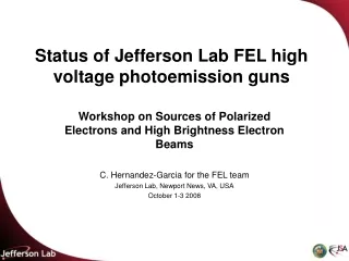
Status of Jefferson Lab FEL high voltage photoemission guns Workshop on Sources of Polarized Electrons and High Brightness Electron Beams C. Hernandez-Garcia for the FEL team Jefferson Lab, Newport News, VA, USA October 1-3 2008
The JLab IR Free Electron Laser (FEL) holds the world’s average power record at 14 kW (l=1.06 mm) with 8.5 mA CW electron beam current The JLab FEL is an Energy Recovery Linac, Fourth Generation Light Source.
FEL vault Gun Test Stand The FEL operates two similar DC un-polarized photoemission guns. One gun powers the FEL injector. 60 meters The other gun is a test stand with characterization beam line
Outline • General description of the FEL-type photoguns • FEL gun operated at 350kV and ~10 mA CW for FEL operations • Photocathode performance • High voltage performance • GTS gun operated at >350kV and 10 Hz rep rate for beam characterization • Photocathode performance • High voltage performance • Concepts for next generation design • Load-lock chamber • Inverted insulator?
The DC gun consists of electrodes that hold the photocathode inside a vacuum chamber. The electrodes are electrically isolated by ceramic insulators RGA, extractor gauge and leak valve High voltage feed Photocathode retractor mechanism Ceramic insulators Photocathode Electrodes Corona shield 33 inches Vacuum chamber NEG pumps
Internal Cesiation Retractable photocathode stalk 40 cm HV conditioning Shield door The GaAs wafer is activated into a Negative Electron Affinity (NEA) photocathode by forming a Cs-NF3 surface layer Drive Laser
Electron bunches are generated when the GaAs photocathode is illuminated by pulses of green light from a drive laser
Vacuum procedures • The electrodes and all internal gun components are cleaned using ultra-sonic baths of de-greaser solution and rinsed with de-ionized water • The entire gun assembly are performed in a clean-room class 1000 enclosure • The gun assembly is then baked at 250ºC until the pressure drop in 24 hours is less than 10%. Hydrogen dominated vacuum environment
GaAs wafer 25 mm dia Active area 16 mm dia Drive laser 8 mm dia The FEL gun delivered over 7000 Coulombs and over 900 hours of beam time at 1-8.5 mA CW with a single wafer, which was activated into a photocathode a total of 9 times in 36 months of operation with an average of 6 re-cesiations per activation The picture shows the photocathode being illuminated with the drive laser
The FEL 1/e photocathode lifetime is 550 Coulombs at 5 mA CW
FEL gun high voltage performancea series of fortunate events…
FEL gun high voltage performanceand a series of unfortunate events…
FEL gun high voltage performanceand a series of unfortunate events…
The GTS (Gun Test Stand)was built for • Testing gun high voltage performance with coated electrodes for field emission suppression • Dedicated operations for electron beam characterization at low duty factor and high charge
Incoming drive laser beam Anode/mirror plate 12 inches The FEL and the GTS guns are identical in design and dimensions except for two features • The anode plate in the GTS gun is used as a mirror for reflecting off the drive laser and illuminating the photocathode at a 40 degree angle.
2. The electrodes in the GTS gun are coated with a field emission suppression film. The support tube electrode starts as a single block of cross-forged, vacuum arc re-melt stainless steel. Then it is machined, hand-polished, cleaned and plasma-sputtering coated Support tube, 12.4 MV/m Ball cathode, ~ 8 MV/m GaAs wafer ~6.0 MV/m Note: Field strengths calculated for 500 kV 25 cm
SiOxNy films§ have demonstrated field emission suppression by more than 5 orders of magnitude compared to bare polished stainless steel electrodes (27 μA at 16 MV/m)* but had never been tried on actual gun electrodes until now § N. D. Theodore et al., IEEE TRANSACTIONS ON PLASMA SCIENCE, VOL. 34, NO. 4, AUGUST 2006, pp 1074-1079. * C. Sinclair et al., Proceedings of the 2001 Particle Accelerator Conference, Chicago, pp.
The gun chamber was vacuum fired in-house at 400 Celsius for 160 hours
Phil Adderley and Marcy Stutzman measured the Hydrogen out-gassing rate. The chamber was not vented after being heat treated when the measurement was done. The out-gassing rate could then be different in the operational gun after the chamber was vented for the gun assembly and re-baked at 250C.
GTS photocathode performance • With the gun assembled, measured 1E-11 Torr after standard bakeout procedure at 250° C • While configuring the gun for high voltage operations, a leak in the 14 inch flange gasket opened up • Achieved ~15% QE, but cathode dark lifetime very poor (a few hours) due to initial leak • Achieved first beam on March 14 2008 at 300 kV
GTS high voltage performance • It took 22 days, or 528 hours, to go from 130kV to 485kV, that’s ~0.75 kV per hour • In contrast, the FEL gun took about 80 man-hours to condition to 420 kV with the slowest pace at 3 kV/hour • Field emission suppression coating might have contributed to excessive gas desorption during high voltage conditioning compared to FEL bare electrodes • Conditioning was slowed down by multiple problems
To eliminate space charge effect, the cathode was illuminated with a DC laser at very low fluence. This verified the cathode QE uniformity, the transport system and the diagnostics. The lines are due to interference going through the pick-off window. The round fringes are Fresnel diffraction ripple due to the aperture in the laser transport Electron beam image on the viewer screen mapping the laser beam spot on the cathode Picture of the laser beam spot delivered to the cathode
Some of the issues… • High voltage reliability • Electrode surfacing/cleaning for reduced field emission • Bulk resistivity and/or segmented insulators for charge dissipation • Kovar to ceramic braze reliability for vacuum compatibility • Etc… • Vacuum improvements for better photocathode lifetime at high average current • Vacuum firing and better materials for lower hydrogen out-gassing rate • Better pumping and/or different gauges?...
A possible next generation gun design • Will be based on CEBAF/Cornell load-lock systems • Will explore CEBAF’s new approach of inverted insulator… Picture courtesy of Matt Poelker
More details towards more robust, next generation DC photoemission guns to be discussed later today THANK YOU
The quantum efficiency drops during average current operation when the electron beam ionizes residual gas in the gun vacuum chamber. (Coulombs)
The positive ions are accelerated by the electrostatic field impacting on the wafer surface degrading the quantum efficiency and causing crystal structure damage Crystal structure damage to the electrostatic center Illuminated area by drive laser light Illuminated area by drive laser light 25 mm The Quantum Efficiency of a recently activate photocathode is around 5-7% The Quantum Efficiency of an used photocathode drops to about 1% Picture of a damaged GaAs wafer after delivering over 8 mA of average current during one year of operation
60 inches 12 inches Semi-load lock system for the GTS • A design of a semi-load lock system for replacing cathodes without perturbing the gun chamber vacuum has been completed and fabrication awarded to McAllister Inc. This system will also allow re-cesiation without opening the SF6 tank, shortening the process from 3.5 to 0.5 hours. Bellows The bellows are extended to retract the cathode stalk and the valve is closed Valve The bellows are compressed to insert the cathode stalk with the valve open. The compressed bellows fit within the corona shield
What happens when the photoemission current goes unstable? DekTek profile shows the crater is 40 microns deep with a central peak 40 microns high The photocathode arcs, leaving a crater behind. EDS profile across crater shows As depletion where Ga concentration peaks
SEM pictures of the crater give some sense of the local high temperature during the arc
GaAs wafer 25 mm dia Active area 16 mm dia Drive laser 8 mm dia Despite this kind of damage, the GaAs wafer is made operational again by heat cleaning at 550° C and re-activating into a NEA photocathode All that process performed under vacuum conditions inside the gun vacuum chamber