Download

1 / 35
350 likes | 375 Views
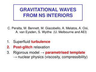
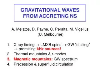
Power from the waves. An inventor’s paradise. Ocean wave energy conversion has inspired hundreds of Patents, not all of them very practical………. Generator. Oscillating air flow. Flotation chamber. Masuda buoy. Japanese wave-powered navigation buoy, first introduced in 1960’s.

E N D
An inventor’s paradise Ocean wave energy conversion has inspired hundreds of Patents, not all of them very practical……….
Generator Oscillating air flow Flotation chamber Masuda buoy Japanese wave-powered navigation buoy, first introduced in 1960’s. Overall diameter 3m. Air turbine and 60W generator, powered by oscillating water column. Output stored in lead-acid batteries.
Artist’s impression of full-scale NEL OWC devices. Could use a floating, moored structure (shown here) or be mounted on sea bed
Cockerell raft wave energy converter Funded under UK wave energy programme in the 1980s Segmented raft flexes under wave action. Power take-off using high-pressure hydraulics. 1/10-scale prototype tested in the English channel
Salter’s Duck Funded under UK wave energy programme in the 1980s. Schematic view of cross-section Angular motion between duck and spine actuates hydraulic pumps for power take-off
Salter’s Duck Model duck under test in extreme wave conditions in the laboratory. With optimum damping, extraction efficiencies close to 100% are achievable
Testing of ducks at about 1/10 scale in Loch Ness, late 1980s. Each duck is free to take up its own angular position relative to the common spine
Bristol cylinder Buoyant cylinders, tethered just below surface, move in a circular path in waves. Submerged hydraulic pumps extract power
“Clam” air-bag energy converter Flexible air-bags attached to a rigid framework. Flexing of the bags due to wave action drives air through flow passages in the structure. Power take-off uses Wells air turbines directly coupled to generators
Backward bent duct buoy (BBDB) Oscillating water column device, with leeward opening to the sea
Hose-pump Floats tethered to sea-bed by elastomeric tube. Pressurised sea-water pumped through non-return valves to turbine
Norwegian OWC 500 kW prototype device on shoreline near Stavanger. Concrete OWC chamber topped by steel tubular tower. Single-rotor Wells turbine. Constructed in 1985, destroyed by storm in 1988
Norwegian OWC schematic Generator Wells turbine Circular splash guard with annular space for air flow to turbine OWC chamber
Wells turbine Sectioned model of a twin-rotor, 500 kW turbine similar to that fitted to the Limpet OWC on Islay Generator No. 1 rotor Supporting strut No.2 rotor Butterfly valve
Norwegian tapered channel system Constructed in 1985, operated successfully for ten years
Aerial view of tapered channel wave power plant Sea Tapered channel Reservoir Turbine house (250 kW)
Islay prototype OWC schematic Generator OWC chamber Wells turbine
Prototype oscillating water column device, Portnahaven, Islay. Wells turbine and generator rated at 75 kW. Constructed in 1985, de-commissioned in 1999
Osprey oscillating water column device Rated at 2 MW output. Located in shallow water using sand-filled ballast tanks. Prototype constructed in 1995, but damaged by storm during deployment off Scottish coast near Dounreay.
Wave Dragon A Danish design: the arms amplify the incoming waves which spill over into a central chamber. Power take-off uses simple low-head hydro power technology An artist’s impression of the device. At full scale, it would be 260 m wide and would develop up to 4 MW
A small-scale model of the Wave Dragon on test in a wave tank
A 1/4.5 scale prototype Wave Dragon during sea trials off the Danish coast, 2003
Archimedes Wave Swing Concept developed in the Netherlands; a submerged device with a vertically heaving float connected to a linear electrical generator Prototype rated at 2MW, shown here on tow in preparation for sea trials off the coast of Portugal, early 2002
500 kW rated, shoreline mounted oscillating water column device near Portnahaven, Islay
Actual 500 kW Wells turbine being prepared for installation in Limpet OWC on Islay
Pelamis wave energy conversion device A floating attenuator, Pelamis consists of 4 linked cylindrical elements. Flexing of joints between elements actuates hydraulic rams which feed oil into a high-pressure reservoir. Power take-off is via a hydraulic motor to an electrical generator Artist’s impression of a “farm” of Pelamis machines in a staggered array. Full-scale device is 120 m long, 3.5 m in diameter and develops 750 kW
1/7 scale Pelamis in sea trials in the Firth of Forth near Edinburgh, 2001
Pelamis power conversion module Hydraulic ram High pressure accumulator Hydraulic motor and generator Fluid reservoir Hinged joint
Global ocean wave energy resource(annual averages in kW/m width of wave)