Download
1 / 45
450 likes | 468 Views
Explore the Laser Compton e+ source for the International Linear Collider (ILC). Understand the significance of the Stacking Cavity R/D in Japan and France, focusing on collaborative efforts and experimental methods to enhance positron polarization efficiently. Learn about the challenges and advantages of different sources and how the Laser Compton approach offers independence and ease of operation. Drive towards achieving high enhancement factors and small spot sizes with proposed cavity configurations.

E N D
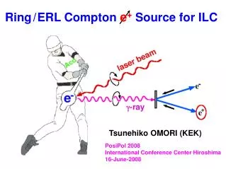
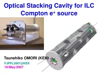
Optical Stacking Cavity for ILC Compton e+ source Tsunehiko OMORI (KEK) FJPPL2007@KEK 10/May/2007
FJPPL optical cavity Compton collaboration France Japan F. Zomer (LAL) A. Variola (LAL) V. Soskov (LAL) M. Jacquet (LAL) A. Vivoli (LAL) R. Chiche (LAL) R. Cizeron (LAL) Y. Fedala (LAL) D. Jehanno (LAL) T. Omori (KEK) J. Urakawa (KEK) N. Terumuma (KEK) M. Kuriki (KEK) S. Araki (KEK) T. Takahashi (Hiroshima Univ.) H. Shimizu (Hiroshima Univ.) N. Sasao (Kyoto Univ.) M. Washio (Waseda Univ.) T. Hirose (Waseda Univ.) K. Sakaue (Waseda Univ.)
Today's Talk 1. Laser Compton e+ source for ILC. 2. Why Stacking Cavity R/D 3. R/D in Japan 4. R/D in France 5. World-wide collaboration 6. Summary
ILC: International Linear Collider DR e-lineac e+ lineac DRs ~ 50 km Ecm = 500 - 1000 GeV start experiment at ~2020 Polarized Beams play important role Suppress back ground Increase rate of interaction (if both beam pol) Solve Week mixing of final state
ILC positron sources undulator-based e+ source base line choice 1st stage: non-polarized source later: upgrade to polarized source 2) Compton-based e+ source advanced alternative polarized source 3) Conventional e+ source back up non-polarized source
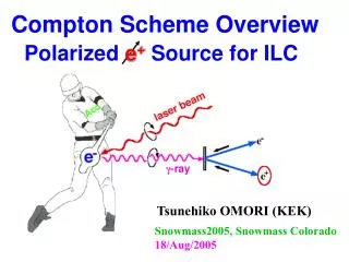
Two ways to get pol. e+ (1) Helical Undurator e- beam E >150 GeV Undulator L > 200 m (2) Laser Compton
Two ways to get pol. e+ (1) Helical Undurator e- beam E >150 GeV Undulator L > 200 m Our Proposal (2) Laser Compton
Why Laser Compton ? i) Positron Polarization. ii) Independence Undulator-base e+ : use e- main linac Problem on design, construction, commissioning, maintenance, Laser-base e+ : independent Easier construction, operation, commissioning, maintenance iii) Low energy operation Undulator-base e+ : need deccelation Laser-base e+ : no problem
ILC Undulator-base e+ Source 150 GeV 250 GeV 250 GeV Experiments
Ring Base Compton (an example) Re-use Concept laser pulse stacking cavities efficient photon beam positron stacking in main DR Electron storage ring (or ERL) efficient electron beam to main linac
325 MHz 325 MHz Laser Pulse Stacking Cavity Laser-electron small crossing angle Laser bunches Lcav = n Lcav = m Llaser Cavity Enhancement Factor = 1000 - 105
Why Stacking Cavity R/D? a) The most uncertain part of the current design. b) The efficiency of whole system highly depends on the optical cavity design. laser spot size collision angle enhancement factor Simulation alone is not effective in desiging cavity. We need experimental R/D.
R/D in Japan Moderate Enhancement ~ 1000 Moderate spot size ~ 30 micron Simple cavity stucture with two mirrors Get experinence with e- beam
Experimental R/D in ATF Hiroshima-Waseda-Kyoto-IHEP-KEK Make a fist prototype 2-mirror cavity Lcav = 420 mm . Put it in ATF ring
Points of R/D Achieve both high enhancement & small spot (less stabile) & (less stabile) Points for high enhancement factor remove/suppress vibration establish feed-back technology Points for small spot 2 - Lcav --> +0 good matching between laser and cavity all are common in pol. e+ and laser wire
10W, 357MHz 8000 6000 Counts/crossing 4000 2000 0 0 10 20 30 crossing angle Points of R/D (continued) Achieve smaller crossing angle Number of -rays strongly depends on crossing angle ATF e- bunch length = 9 mm (rms) Ne = 1x10¹⁰/bunch --> Small crossing angle is preferable --> constraint in chamber design This in NOT common in pol. e+ and laser wire
Laser stacking cavity with Two Spherical Mirrors Choice of R and spot size L R L = 420.00 mm our choice for 1st prototype concentric configuration R + R ~ L
e- beam laser beam
e- beam laser beam
e- beam laser beam
e- beam laser beam
e- beam laser beam
Optical Cavity Vacuum chamber
Preparation and Schedule End/2006 Parts of the Optical Cavity delivered March Pre-Assemble Optical Cavity done May Vacuum chamber delivered July-Jul Assemble whole system and make test at outside ATF-DR Summer Install prototype cavity into ATF-DR Oct-Dec First gamma-ray generation test
Expected Number of g-rays Number of g-rays/bunch Electron :Ne = 2x10¹⁰ (single bunch operation) Laser : 10 W (28 nJ/bunch) Optical Cavity: Enhancement = 1000 Ng =1300/bunch X-ing angle = 10 deg Ng = 900/bunch X-ing angle = 15 deg Number of g-rays/second Electron :Ne =1x10¹⁰ (multi-bunch and multi-train operation) Electron 20 bunches/train, 3 trains/ring Laser : 10 W (28 nJ/bunch) Optical Cavity: Enhancement = 1000 Ng = 8.5x10¹⁰/sec X-ing angle = 10 deg Ng = 5.7x10¹⁰/sec X-ing angle = 15 deg
R/D in France Very High Enhancement ~ 20000 - 100000 Small spot size ~ 5 micron Sofisticated cavity stucture with 4 mirrors Start with no e- beam Later we will make a e- beam compatible cavity
4-mirror-cavity ---> separate functions & confocal configuration
2-mirror cavity 4-mirror cavity R1=R2=L R1=R2=L/2 L L confocal concentric
R/D in France and in Japan are Complementary R/D in France Very High Enhancement ~ 20000 - 100000 R/D in Japan Moderate Enhancement ~ 1000
R/D in France and in Japan are Complementary R/D in France Very High Enhancement ~ 20000 - 100000 Small spot size ~ 5 micron R/D in Japan Moderate Enhancement ~ 1000 Moderate spot size ~ 30 micron
R/D in France and in Japan are Complementary R/D in France Very High Enhancement ~ 20000 - 100000 Small spot size ~ 5 micron Sofisticated cavity stucture with 4 mirrors R/D in Japan Moderate Enhancement ~ 1000 Moderate spot size ~ 30 micron Simple cavity stucture with two mirrors
R/D in France and in Japan are Complementary R/D in France Very High Enhancement ~ 20000 - 100000 Small spot size ~ 5 micron Sofisticated cavity stucture with 4 mirrors Digital feedback R/D in Japan Moderate Enhancement ~ 1000 Moderate spot size ~ 30 micron Simple cavity stucture with two mirrors Analog feedback
R/D in France and in Japan are Complementary R/D in France Very High Enhancement ~ 20000 - 100000 Small spot size ~ 5 micron Sofisticated cavity stucture with 4 mirrors Digital feedback Start with no e- beam R/D in Japan Moderate Enhancement ~ 1000 Moderate spot size ~ 30 micron Simple cavity stucture with two mirrors Analog feedback Get experinence with e- beam
R/D in France and in Japan are Complementary R/D in France Very High Enhancement ~ 20000 - 100000 Small spot size ~ 5 micron Sofisticated cavity stucture with 4 mirrors Digital feedback Start with no e- beam Later we will make a e- beam compatible cavity R/D in Japan Moderate Enhancement ~ 1000 Moderate spot size ~ 30 micron Simple cavity stucture with two mirrors Analog feedback Get experinence with e- beam
R/D in France and in Japan are Complementary R/D in France Very High Enhancement ~ 20000 - 100000 Small spot size ~ 5 micron Sofisticated cavity stucture with 4 mirrors Digital feedback Start with no e- beam Later we will make a e- beam compatible cavity R/D in Japan Moderate Enhancement ~ 1000 Moderate spot size ~ 30 micron Simple cavity stucture with two mirrors Analog feedback Get experinence with e- beam
World-wide Collaboration PosiPol Collaboration Collaborating Institutes: BINP, CERN, DESY, Hiroshima, IHEP, IPN, KEK, Kyoto, LAL, NIRS, NSC-KIPT, SHI, Waseda, BNL, and ANL Sakae Araki, Yasuo Higashi, Yousuke Honda, Masao Kuriki, Toshiyuki Okugi, Tsunehiko Omori, Takashi Taniguchi, Nobuhiro Terunuma, Junji Urakawa, X. Artru, M. Chevallier, V. Strakhovenko, Eugene Bulyak, Peter Gladkikh, Klaus Meonig, Robert Chehab, Alessandro Variola, Fabian Zomer, Alessandro Vivoli, Richard Cizeron, Frank Zimmermann, Kazuyuki Sakaue, Tachishige Hirose, Masakazu Washio, Noboru Sasao, Hirokazu Yokoyama, Masafumi Fukuda, Koichiro Hirano, Mikio Takano, Tohru Takahashi, Hirotaka Shimizu, Shuhei Miyoshi, Akira Tsunemi, Li XaioPing, Pei Guoxi,Jie Gao, V. Yakinenko, Igo Pogorelsky, Wai Gai, and Wanming Liu POSIPOL 2007 LAL-Orsay, France 23-25 May POSIPOL 2006 CERN April 2006 http://events.lal.in2p3.fr/conferences/Posipol07/ http://posipol2006.web.cern.ch/Posipol2006/
World-Wide-Web of Laser Compton 4th Generation light source ERL CLIC e+ Laser Compton ILC e+ Polari- metry gg collider Optical Cavity X-ray source Medical applications LW monitor High power laser e- source ILC, ERL Industrial applications
Summary 1. Compton e+ source is an advanced alternative of ILC e+ source 2. Laser stacking cavity is a key. 3. In Japan, we are preparing -ray generation by installing the stacking cavity in ATF-DR. 4. In France, we are developing a very advanced cavity with 4 mirrors. In future, a 4-mirror cavity will be installed in ATF-DR for -ray generation. 5. We have a world-wide collaboration for Compton. Not only for ILC e+ source. Also for many other applications.
Cavity History in Japan by H. Sato (Posipol 2006)
e- beam optics DR North Straight Section by T. Okugi
e- beam optics and spot size s = 40 m (=s0) (between QM13R and QM14R) Twiss Parameter alpha_x = -0.092 m beta_x = 6.155 m eta_x = 0 m alpha_y = -0.232 m beta_y = 6.546 m eta_y = 0 m Assume eps_x = 1.0E-09 m eps_y = 0.5E-11 m e- beam spot size sig_x (s0) = 78 um sig_y (s0) = 6 um Stay almost constant in S = +- 1 m
Collision Point Collision point is at between QM13R and QM14R (s = 40 m) .