Download
1 / 31
310 likes | 331 Views
This presentation discusses the suppression of injection perturbations using feed-forward techniques in beam position acquisition and feedback systems at ALBA Synchrotron. It explores the challenges posed by the injection system and proposes a feedforward approach for efficient use of corrector bandwidth and better beam position correction.

E N D
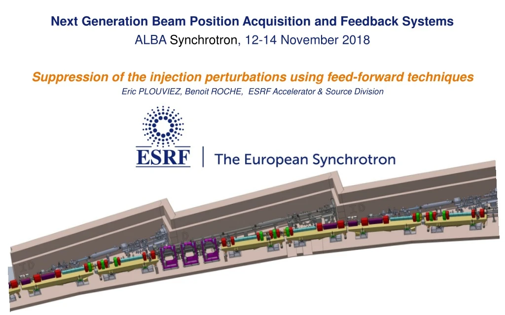
Next Generation Beam Position Acquisition and Feedback Systems ALBA Synchrotron, 12-14 November 2018 Suppression of the injection perturbations using feed-forward techniques Eric PLOUVIEZ, Benoit ROCHE, ESRF Accelerator & Source Division
MOTIVATION OF OUR DEVELOPEMENTS • TOP UP OPERATION • (one refill every 20 minutes instead of twice a day) • we need to address a new kind of beam position perturbation; • The injection system (kickers and septum) causes • beam position oscillation which is perturbing our users experiments. • Specificity: Reproducible shape , triggered by the injection . kickers Page 2 Next Generation Beam Position Acquisition and Feedback Systems, 12-14 November 2018
MOTIVATION OF THIS TALK • I DO NOT PRETEND THAT ANYTING IS REALLY • TECHNICALLY ORIGINAL IN OUR SYSTEMS • BUT I THINK IT IS INTERESTING TO PRESENT • THIS APPROACH IN THE FRAME OF THIS WORKSHOP • IN ORDER TO COMPARE IT TO WHAT COULD BE ACHIEVED • WITH PURE FEEDBACK SYSTEMS Page 3 Next Generation Beam Position Acquisition and Feedback Systems, 12-14 November 2018
ESRF storage ring injection scheme Classical four kickers bump scheme • Injection induced perturbation: • Septum field leakage • Non closure of the bump during the rise and fall of the bump due to the presence of sextupoles inside the bump kickers Page 4 Next Generation Beam Position Acquisition and Feedback Systems, 12-14 November 2018
ESRF storage ring injection scheme ~19mm kickers Same power supply • Pulsed elements at the end of the transfer line: • 2 active septa S1 and S2 • 1 in-vacuum septum Page 5 Next Generation Beam Position Acquisition and Feedback Systems, 12-14 November 2018
kickers septum Stored beam path Injected beam path PARASITIC BEAM POSITION OSCILLATION DURING THE INJECTION IN THE SR septum The injection kick path includes sextupoles => the kicker bump is not closed during the kick rise time and fall time There is a small leakage of the septum field Next Generation Beam Position Acquisition and Feedback Systems, 12-14 November 2018
Effect on the horizontal beam position Perturbation oBservedoN THE HORIZONTAL BEAM POSITION 4 mm 4 mm 1000 turns = 2.8ms 1000 turns 3 turns 2.8ms =1turn Blue:kick shape Purple: sextupole effect Next Generation Beam Position Acquisition and Feedback Systems, 12-14 November 2018
LIMITED FEEDBACK EFFECT Orbit Correction Feedback : • Limited bandwidth (compared to the available correctors bandwidth) • Limited kicker strength. • Instability Feedback: • Limited kicker strength • Limited bandwidth (compared to the available correctors bandwidth) Page 8 Next Generation Beam Position Acquisition and Feedback Systems, 12-14 November 2018
EFFECT OF THE FAST ORBIT CORRECTION ON THE KICK DUE TO THE SEPTUM Orbit Correction Feedback bandwidth: 150Hz Corrector strength: Parasitic kick strength: The correction signal results in overshoot without real reduction of the perturbation peak amplitude. Sometime the orbit correction stops due to an excessive demand on the corrector strength The corrector bandwidth is 500Hz which is enough to generate a correction signal, so how can we use it more efficiently? Page 9 Next Generation Beam Position Acquisition and Feedback Systems, 12-14 November 2018
FEEDFORWARD APPROACH FOR THE FAST ORBIT CORRECTION: Correction signal stored in a look up table : • Efficient use of the corrector bandwidth: • No loop stability problem • Allows some bandwidth extension by pre emphasis of the signal • Better use of the available correction strength: • Correction spread over 6 correctors instead of 2 when the correction is calculated by the feedback loop using the standard SVD derived correction matrix Page 10 Next Generation Beam Position Acquisition and Feedback Systems, 12-14 November 2018
Normal Fast Orbit Correction effect: Correction calculated with the normal orbit correction matrix : • Will use mostly two correctors The feedback bandwidth is 150Hz: • The correction will be produced with a delay of about 2ms => no effect! Efficient use of the corrector bandwidth Efficient use of the corrector bandwidth Close to the maximum corrector strength Page 11 Next Generation Beam Position Acquisition and Feedback Systems, 12-14 November 2018
Orbit correction: feedforward correction We can use more correctors : • 6 correctors are available between the two ID straight sections surrounding the injection straight section The correction generation is triggered by the injection timing • no delay • Correction signal generation is fully using the 500Hz correctors bandwidth Efficient use of the corrector bandwidth Efficient use of the corrector bandwidth Page 12 Next Generation Beam Position Acquisition and Feedback Systems, 12-14 November 2018
Orbit correction: feedforward correction Efficient use of the corrector bandwidth Efficient use of the corrector bandwidth 50 ms CORRECTION KICKS CANCELLING THE SEPTUM LEAK TIME DOMAIN WAVEFORM USED TO MODULATE THE CORRECTION KICKS Page 13 Next Generation Beam Position Acquisition and Feedback Systems, 12-14 November 2018
Orbit correction: feedforward correction Efficient use of the corrector bandwidth Efficient use of the corrector bandwidth MAXIMUM ORBIT PERTURBATION DURING THE SEPTUM PULSE Page 14 Next Generation Beam Position Acquisition and Feedback Systems, 12-14 November 2018
kickers septum Stored beam path Injected beam path PERTURBATION DUE TO THE INJECTION KICKERS sextupoles Efficient use of the corrector bandwidth Efficient use of the corrector bandwidth 2.8ms =1turn Blue:kick shape Purple: sextupole effect Page 15 Next Generation Beam Position Acquisition and Feedback Systems, 12-14 November 2018
PERTURBATIONS CAUSED BY THE INJECTION KICKERS KICKERS STRENGTH: .5 mrad SPURIOUS KICKS DUE TO THE SEXTUPOLES: .05 mrad PURELY ACTIVE CANCELLATION WOULD REQUIRE VERY STRONG CORRECTORS Efficient use of the corrector bandwidth Efficient use of the corrector bandwidth PASSIVE CANCELLATION BY: SHAPING THE KICKERS FIELDS (DIPOLE +QUADRUPOLE) ADDING AN OCTUPOLE IN THE BUMP Page 16 Next Generation Beam Position Acquisition and Feedback Systems, 12-14 November 2018
l Bunch cleaning & Beam stabilisation 29th of January 2016 E. Plouviez PASSIVE COMPENSATION 1ms 1ms 1ms Perfect compensation: Two parabolic shaped kicks of 1ms separated by 1ms; Second sextupole First sextupole Parasitic kick: d*K(t)2 How can we generate: K(t) - d*K(t)2 instead of K(t) ? K(t) - d*K(t)2 = K(t) *(1- d*K(t)) we can get the *(1- d*K(t))factor from the B field variation with dx inside the kicker magnet: B= B0 - (b*dx)
Kicker passive compensation • Idea: add copper shims inside the kickers ferrite gap to generate a non-linear field • Shape this field with the shims dimension in order to cancel the sextupole field: reduction of both beta-beat and orbit distortions • Creates vertical field gradient: alignment is now critical Presently installed • Ideal conditions and 18mm bump amplitude, simulations indicate a factor 3 improvement Courtesy Simon White Page 18 Next Generation Beam Position Acquisition and Feedback Systems, 12-14 November 2018
Page 19 Next Generation Beam Position Acquisition and Feedback Systems, 12-14 November 2018
ADDITION OF AN OCTUPOLE ACTUALLY THE FULL PASSIVE COMPENSATION OF THE SEXTUPOLES EFFECT REQUIRED ALSO THE IMPLEMENTATION OF AN OCTUPOLE IN ORDER TO FULLY CANCEL THE TRANSIENT QUADRUPOLE FIELD EFFECT WICH RESULTED IN A BEAM BLOW UP DURING THE BUMP CREATION Efficient use of the corrector bandwidth Efficient use of the corrector bandwidth Page 20 Next Generation Beam Position Acquisition and Feedback Systems, 12-14 November 2018
SITUATION AFTER THE SHIMS AND OCTUPOLE IMPLEMENTATION VERTICAL POSITION OSCILLATION CYAN: HORIZONTAL POSITION OSCILLATION BLUE: VERTICAL POSITION OSCILLATION Efficient use of the corrector bandwidth Efficient use of the corrector bandwidth HUGE REDUCTION OF THE HORIZONTAL PERTURBATION STILL A VERTICAL PERTURBATION DUE TO A MORE DIFFICULT ALIGNEMENT OF THE KICKERS (NOW DIPOLE/QUADRUPOLE) Page 21 Next Generation Beam Position Acquisition and Feedback Systems, 12-14 November 2018
ADDITIONAL ACTIVE CORRECTION REQUESTED BANDWITH: around 1 MHz REQUESTED KICKER STRENGTH: 6mrad (H) and 2mrad (V) STRIPLINE KICKERS: .5mrad MAGNETIC KICKERS: 4mrad Efficient use of the corrector bandwidth Efficient use of the corrector bandwidth BUT ONLY ONE STRIPLINE OR MAGNETIC KICKER AVAILABLE => no closed bump correction possible TRANSVERSE DAMPING TIME : 6ms => a perturbation suppression obtained over a several 2.8ms revolutions will still be very beneficial. And it reduces also the necessary kicker strength Page 22 Next Generation Beam Position Acquisition and Feedback Systems, 12-14 November 2018
SR magnetic shaker • 400W amplifier => 4 A peak current • 6 coils • Set up bandwidth: 1 MHz • 6 Gev beam, B field effect => 4 mrad peak /turn Page 23 Next Generation Beam Position Acquisition and Feedback Systems, 12-14 November 2018
ACTIVE CORRECTION SCHEME The chromaticity on the ESRF storage ring is high, especially in the vertical plane => Due to the decoherency the correction cannot be done over a too large number of turns Efficient use of the corrector bandwidth Efficient use of the corrector bandwidth HORIZONTAL CORRECTION OVER 9 TURNS (H tune= .44) VERTICAL CORRECTION OVER 5 TURNS (V tune = .39) CORRECTION SIGNAL GENERATED USING A LOOK UP TABLE. Page 24 Next Generation Beam Position Acquisition and Feedback Systems, 12-14 November 2018
CORRECTION SIGNAL CALCULATION • PERTURBATION SHAPE MEASUREMENT: • BPM pick up: • 4 buttons with RF matching transformers • Signal processor: • ADC data from an Itech Spark => 304 samples per turn,1014 samples Efficient use of the corrector bandwidth Efficient use of the corrector bandwidth For each of the 304 samples we get the amplitude and phase of the perturbation over 9 turns (horizontal) or 5 turns (vertical) , assuming it is an oscillation at the betatron frequency , and we use these data and the phase shift between the BPM pick up and the corrector to calculate a correction signal …. Page 25 Next Generation Beam Position Acquisition and Feedback Systems, 12-14 November 2018
DAMPING OF THE HORIZONTAL PERTURBATION OVER 9 TURNS 5 turns 600mm rms oscillation: Without active damping: 100mm with damping: 50mm normal beam size: 350mm Page 26 Next Generation Beam Position Acquisition and Feedback Systems, 12-14 November 2018
DAMPING OF THE VERTICAL PERTURBATION OVER 5 TURNS 100mm 5 turns rms oscillation: without active damping: 25mm with damping:10mm normal beam size: 15mm Page 27 Next Generation Beam Position Acquisition and Feedback Systems, 12-14 November 2018
IMPROVED DAMPING OF THE VERTICAL PERTURBATION BY ADDING A STRIPLINE Left : damping with the shaker Right: damping using the shaker and the stripline Page 28 Next Generation Beam Position Acquisition and Feedback Systems, 12-14 November 2018
Addition of the vertical stripline Left : damping with the shaker Right: damping using the shaker and the stripline
OPEN ISSUES RANDOM PERTURBATION PATTERN Efficient use of the corrector bandwidth Efficient use of the corrector bandwidth PERTURBATION MEASUREMENT OVER ONE TURN CORRECTION CALCULATION AND GENERATION OVER A FEW EXTRA TURNS Page 30 Next Generation Beam Position Acquisition and Feedback Systems, 12-14 November 2018
THANKS FOR YOUR ATTENTION Page 31 Next Generation Beam Position Acquisition and Feedback Systems, 12-14 November 2018