Download
1 / 17
170 likes | 215 Views
Explore the journey of SRF operation at NSRRC, showcasing developments, operational parameters, and critical events. Discover solutions, surface treatments, and performance analysis of SRF modules.

E N D
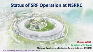
Status of SRF Operation at NSRRC Chaoen WANG On behalf of RF Group National Synchrotron Radiation Research Center (NSRRC) CWRF Workshop, Hsinchu, June. 25th-29th, 2018
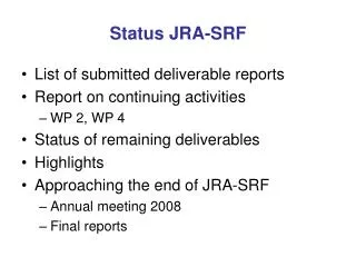
Outline • Review of SRF operation at NSRRC • Challenges in SRF operation and solutions • Remarks
Two Light Sources Operated at NSRRC 1993 - TLS in routine operation, powered by two room temperature cavities, Doris cavities. TLS suffered from longitudinal coupled-bunch instabilities via beam cavity interaction. 2000 - Obtained agreement for SRF technology transfer from Cornell University. 2005 - TLS, routinely operated at 360-mA @ 1.5 GeV, powered by single SRF module of Cornell design. 2007 - Construction project of TPS launched. 2009 - Obtained agreement for SRF technology transfer from KEK. 2015 - Two 500-MHz SRF modules of KEKB design installed at TPS. - Maximum beam current up to 520-mA achieved. 2016 - TPS, routinely operated at 300-mA @ 3.0 GeV, powered by two SRF modules of KEKB design (2*1400 kV). 2017 - TPS, routinely operated at 400-mA @ 3.0 GeV, powered by two SRF modules of KEKB design (2*1600 kV).
500-MHz S/C Cavies operated at NSRRC Cornell-type SRF module (2005~) KEKB-type SRF module (2015~) • Waveguide-typepower coupler; • Flute beam pipe; • Coaxial-typepower coupler; • Large round beam pipe;
Performance of SRF Modules at NSRRC Vertical and Horizontal Test Cornell-type SRF module KEKB-type SRF module Vertical and Horizontal Test Surface treatments • High pressure rinsing (HPR); • BCP; • 2nd HPR after vertical test. Surface treatments • w/o high pressure rinsing (HPR); • Electropolishing (EP 1); • High temperature annealing; • EP 2 and rinsing with pure & ozonized water; • Bake-out of Nb cavity in vacuum; • w/o rising after vertical test. Degradation of Q0? Not Yet!
SRF Operational Parameters at NSRRC • Taiwan Light Source • Taiwan Photon Source • Maximum beam current up to 400 mA demonstrated; • Routine operational beam current ~ 360-mA. • Routine operational RF gap voltage 1.6 MV (one module) • Routine operational RF power ~ 80 kW / per sc cavity • Maximum beam current up to 520 mA demonstrated; • Routine operation beam current ~ 400 mA. • Routine operational RF gap voltage 2*1.6 MV (two modules) • Routine operational RF power ~ 220 kW / per sc cavity • Full thermal cycling once per two year. • Beam processing for individual cavities once per 4 weeks. • RF conditioning of power coupler (aging) for individual cavities once per two weeks. • Last thermal cycling was done in summer, 2009. • Once or twice beam processing per year before releasing the interlock threshold of POB’s vacuum pressure (now 100 nTorr).
Critical Production/Operation Events at NSRRC 2003Failure of RF window of SRF module S2 during its horizontal test because of misuse of waveguide transformer to correct the unexpected low Qext; Identify heavy deformation of niobium waveguide piece owing to mechanical buckling happened during high-pressure test at room temperature, which causes reduction in Qext in a factor of 4. • Identify (local temp rise) and mitigate (using golden fingers) contamination of indium piece of the repaired SRF module S2 during high-power acceptance test at NSRRC, 2005; 2009 Identify manageable helium leakage into insulation vacuum of operating SRF module, S1. 2015Leakage of helium to ambient due to over-cooling of high-power input coupler of #3 SRF module at NSRRC; Cornell-type SRF module KEKB-type SRF module 2016Over-conditioning of high-power main coupler of #3 SRF module during routine coupler aging at NSRRC, up to 420-kW, CW in short time owing to mistuning of bias current for the high-power RF circulator (no damage!). Pf, Klystron [Watt] -35o -40o Loading angle [deg] -45o Pr, cavity [Watt] Circulator bias current [Amp] Pf, cavity [kW] Vc [kV]
RF Operational Statistics at NSRRC(Completed storage ring RF system including SRF Modules, RF transmitters, LLRF systems, cryogenic electronics, local water manifolds, etc.) No single RF trip in 2017 Room for improvement TPS w/ two KEKB-type SRF module TLS w/ one Cornell-type SRF module > 110 h *Jan-May *Jan-May Routine operational RF power up to 80-kW / per cavity Routine operational RF power up to 220-kW / per cavity <150 mA <340 mA ~400 mA ~300 mA MP MP MP
Challenges in SRF Operation for Light Sources (The SRF operation at TLS is in the multipacting-free regime) • False alarm of arc detection • Our solution • Implement dual interlock thresholds – intensity and duration • False alarm of quench detection • Physical Reason • Spontaneous deformation of cavity in “wrong” direction induces Robinson instability • Our solution • Detune the cavity with more negative loading angle & decrease the gain of amplitude loop of LLRF system; • Microphonics induced by pulse movement of tuner stepping motor • Our solution • Implement microstepping controller • Backlash of tuner movement • Our solution • Optimize the LHe bath pressure to avoid crossing zero tuner force during routine operation
Challenges in SRF Operation for Light Sources (SRF Operation at high average RF power but with median RF gap voltage, < 6 MV/m @ 500-MHz) • Lighten mechanical fatigue of indium seal to prolong the service life expectancy • Our solution • TLS has a second cryogenic plant – Its SRF module S1 has been kept at 4.5 K since the summer of 2009! • TPS has an in-line spare main helium compressor. The turbines could not restart after rotation! 2017 2018 2016 368 liter Temp readout offset: 6.9 K (#2); 12.5 K (#3)
Challenges in SRF Operation for Light Sources (SRF Operation at high average RF power but with median RF gap voltage, < 6 MV/m @ 500-MHz) • Lighten mechanical fatigue of indium seal to prolong the service life expectancy • Improve the operational reliability by mitigating the multipacting • Unload the condensed gases routinely by RF conditioning Beam current [mA] #3 Pf [kW] #3 Vc [kV] #3 CPL MIG Vacuum (1 V: 1 nTorr; 2 V:10 nTorr] #3 Cavity CCG Vacuum [nTorr] Enhancement of multipacting owing to development of gas condensation with the course of SRF operation Beam processing is more effective to unload the condensed gas because of traveling wave operation
Beam Processing (BP) vs. RF Conditioning (RF/C) #2 Pf Beam current RF/C (2017/8/14) BP (2017/8/27) #2 CPL Vacuum #2 Loading Angle #2 CPL Vacuum #3 CPL Vacuum #3 Pf #3 Loading Angle #2 Pf RF/C (2017/8/28) #3 CPL Vacuum #2 Loading Angle Beam current BP (2017/2/15) Unable to ignite the multipacting during RF conditioning (coupler aging) does not ensure that the SEC of a conditioned surface is already less than unity! Perhaps, sufficient numbers of seeding electrons are not available to ignite the multipacting. With beam processing, seeding electrons can be much more than required. #3 Pf #2 CPL Vacuum #3 Loading Angle #3 CPL Vacuum #3 CPL Vacuum
Challenges in SRF Operation for Light Sources (SRF Operation at high average RF power but with median RF gap voltage, < 6 MV/m @ 500-MHz) • Lighten mechanical fatigue of indium seal to prolong the service life expectancy • Improve the operational reliability by mitigating the multipacting • Unload the condensed gases routinely by RF conditioning • Minimize outgassing rate • In-situ bakeout of RF window of SRF module after thermal cycling; • Comprehensive warm bias aging. Reduction of outgassing rate after comprehensive coupler warm aging
Challenges in SRF Operation for Light Sources (SRF Operation at high average RF power but with median RF gap voltage, < 6 MV/m @ 500-MHz) • Lighten mechanical fatigue of indium seal to prolong the service life expectancy • Improve the operational reliability by mitigating the multipacting • Unload the condensed gases routinely by RF conditioning • Minimize outgassing rate • In-situ bakeout of RF window of SRF module after thermal cycling; • Comprehensive warm bias aging; • Comprehensive off-line RF conditioning of the high power input coupler (to be done for next SRF module). Comprehensive RF conditioning of room temperature cavity which cannot be applied to sc cavity at cold but we can do that for the power coupler.
Challenges in SRF Operation for Light Sources (SRF Operation at high average RF power but with median RF gap voltage, < 6 MV/m @ 500-MHz) • Lighten mechanical fatigue of indium seal to prolong the service life expectancy • Improve the operational reliability by mitigating the multipacting • Unload the condensed gases routinely by RF conditioning • Minimize outgassing rate • In-situ bakeout of RF window of SRF module after thermal cycling; • Comprehensive warm bias aging; • Comprehensive off-line RF conditioning of the high power input coupler (to be done for next SRF module); • Enlarge external pumping capacity Couple vacuum pressure [1 V = 1 nTorr] Cavity vacuum pressure [nTorr] SBP I/P vacuum pressure [1 V = 1 nTorr] Inner gate valves open Ion pumps slept. • Slow down the saturation of cryo-pumping from the cold cavity surface; • Minimize the residual gas from its neighboring beam lines into sc cavity. LBP I/P vacuum pressure [1 V = 1 nTorr] Ion pumps on Cryo-pumping is not so powerful as we might expect!
Challenges in SRF Operation for Light Sources (SRF Operation at high average RF power but with median RF gap voltage, < 6 MV/m @ 500-MHz) • Lighten mechanical fatigue of indium seal to prolong the service life expectancy • Improve the operational reliability by mitigating the multipacting • Full thermal cycling & SRF operation with bias voltage Beam current [mA] Coupler vacuum pressure [V] Cavity vacuum pressure [nTorr] Applying bias voltage is necessary to suppress the multipacting. Bias voltage induces new-type of multipacting. SRF trip again due to multipacting of power coupler after 36 days of LHe collection. Full thermal cycling has a short memory again multipacting as well.
Remarks and Perspective • Multipacting enhanced by gas condensation is the major obstacle for highly reliable SRF operation with high beam current. • Playing with SRF module, we never get bored! Thank You Very Much for Your Attention!