Download
1 / 3
30 likes | 65 Views
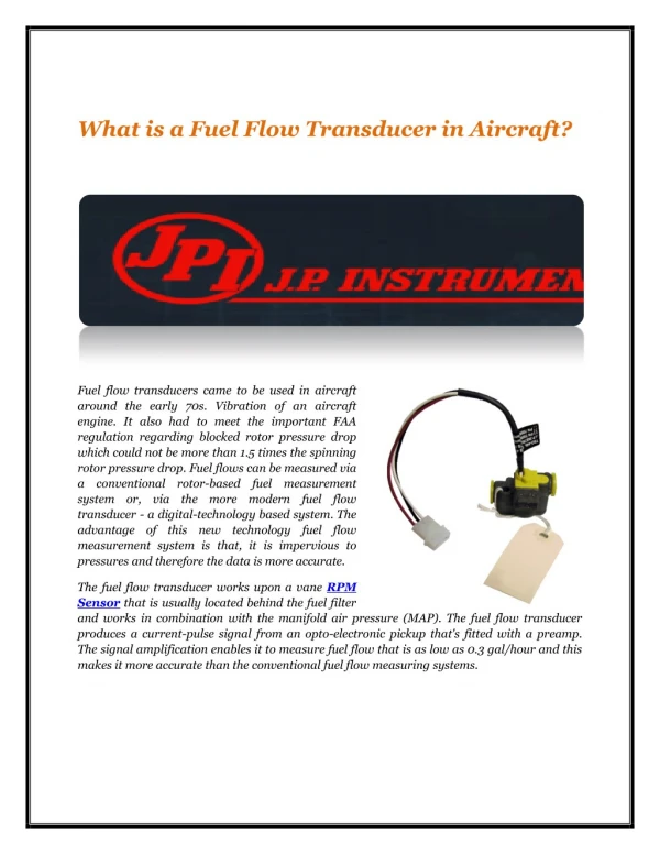
The fuel flow transducer works upon a vane RPM Sensor that is usually located behind the fuel filter and works in combination with the manifold air pressure (MAP). The fuel flow transducer produces a current-pulse signal from an opto-electronic pickup that's fitted with a preamp. The signal amplification enables it to measure fuel flow that is as low as 0.3 gal/hour and this makes it more accurate than the conventional fuel flow measuring systems.

E N D
What is a Fuel Flow Transducer in Aircraft? Fuel flow transducers came to be used in aircraft around the early 70s. Vibration of an aircraft engine. It also had to meet the important FAA regulation regarding blocked rotor pressure drop which could not be more than 1.5 times the spinning rotor pressure drop. Fuel flows can be measured via a conventional rotor-based fuel measurement system or, via the more modern fuel flow transducer - a digital-technology based system. The advantage of this new technology fuel flow measurement system is that, it is impervious to pressures and therefore the data is more accurate. The fuel flow transducer works upon a vane RPM Sensor that is usually located behind the fuel filter and works in combination with the manifold air pressure (MAP). The fuel flow transducer produces a current-pulse signal from an opto-electronic pickup that's fitted with a preamp. The signal amplification enables it to measure fuel flow that is as low as 0.3 gal/hour and this makes it more accurate than the conventional fuel flow measuring systems.
Here's how the Fuel Flow Transducer works: The fuel enters the flow chamber within the fuel flow transducer and begins moving along a helical path. This is to vent out any vapour bubble that might be present in the fuel and result in wrong reading. The rotational velocity of proportional to flow rate. A neutrally buoyant rotor spins with the liquid between V-jewel bearings. Rotor movement is sensed when notches in the rotor interrupt an infrared light beam between an LED and phototransistor. Generally, the fuel flow transducer operates on 12 to 15V consuming just 30 to 50 mA. The red wire is +V power, black is ground and the white wire is signal. Although it contains digital the liquid is directly technology, the fuel flow transducer can operate at temperatures between -55°C to 70°C. If you have a IO-540 300 HP engine with electric and engine driven pumps, the fuel flow transducer should be placed downstream of the engine pump and before the servo. Also, if you have a Rotax 100 ULS (dual carbs), the fuel flow transducer needs to be plumbed in just before the fuel pump – you do not need a second fuel flow transducer. When using a fuel scanner, please use only recommended fuel flow transducers – these are listed in the fuel scanner manual. For e.g. if your fuel scanner is manufactured by JPI use only JPI fuel flow transducers. Although fuel flow transducers work the same, there are minor internal variations and these will match the fuel scanners they are supposed to be paired with. So, using fuel flow transducer from a different manufacturer can result in erroneous Aircraft Fuel Flow Instruments reading. The best fuel flow transducers are manufactured by JP Instruments more information here: https://www.jpinstruments.com/shop/fuel-flow-transducer-231/
JPI Sales: 1-800-345-4574 714-557-3805 FAX: 714-557-9840 sales@jpinstruments.com JPI Technical Support: 1-800-345-4574 714-557-3805 support@jpinstruments.com J.P. Instruments Inc. 3185-B Airway Ave Costa Mesa, CA 9262