Download
1 / 16
160 likes | 180 Views
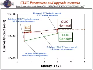
CLIC Parameters and upgrade scenario http://cdsweb.cern.ch/record/1132079/files/CERN-OPEN-2008-021.pdf. 4th phase: 3 TeV luminosity upgrade 3 TeV nominal parameters. 2nd phase: 500 GeV luminosity upgrade 500 GeV nominal parameters. 3rd phase: 0.5 to 3 TeV energy upgrade

E N D
CLIC Parameters and upgrade scenariohttp://cdsweb.cern.ch/record/1132079/files/CERN-OPEN-2008-021.pdf 4th phase: 3 TeV luminosity upgrade 3 TeV nominal parameters 2nd phase: 500 GeV luminosity upgrade 500 GeV nominal parameters 3rd phase: 0.5 to 3 TeV energy upgrade 3 TeV conservative parameters 1rst phase: Initial operation 500 GeV conservative parameters
LC 500 GeV Main parameters @ CLIC08http://clic-meeting.web.cern.ch/clic-meeting/ComparisonTable.html
CLIC main parameters @ CLIC08http://cdsweb.cern.ch/record/1132079?ln=frhttp://clic-meeting.web.cern.ch/clic-meeting/clictable2007.html
CLIC main parameters (proposed)http://cdsweb.cern.ch/record/1132079?ln=frhttp://clic-meeting.web.cern.ch/clic-meeting/clictable2007.html
Power flow @ 500 GeV 129.4 MW Wall Plug Modulator auxiliaries 63.4 MW 61.5 MW hREL = .93 Main beam injection, magnets, services, infrastructure and detector aux = 0.97 hM = .90 Power supplies klystrons hK = .70 1 GHz RF power: 36.1 MW 66 MW hS = .95 Drive beam acceleration hA = .977 hplug/RF = 38.8 % Drive Beam power: 33.5 MW 3.4 MW hRF/main = 39.6 % F(s)= .97 .96 hD = .84 Drive beam power extr. Dumps 26.2 MW hTRS = .98 PETS htot = 7.5 % hT = .96 12 GHz RF power: 24.6 MW (2 x 25 kJ x 50 Hz) hRF = .396 Main linac 9.75 MW Main beam
Power flow @ 3 TeV 415 MW Wall Plug Modulator auxiliaries 260.4 MW AC power 252.6 MW hREL = .93 aux = 0.97 Main beam injection, magnets, services, infrastructure and detector hM = .90 Power supplies klystrons hK = .70 148.0 MW 1 GHz RF power 154.6 MW hS = .95 Drive beam acceleration hA = .977 hplug/RF = 38.8 % 137.4 MW Drive Beam Power 13.7 MW hRF/main = 27.7 % F(s)= .97 .96 hD = .84 Drive beam power extr. Dumps 107.4 MW hTRS = .98 PETS htot = 6.8 % hT = .96 101.1 MW 12 GHz RF power (2 x 101 kJ x 50 Hz) hRF = .277 Main linac 28 MW Main beam
CLIC Plug Power requirements Courtesy: H.Braun
326 klystrons 33 MW, 139 ms combiner rings Circumferences delay loop 80.3 m CR1 160.6 m CR2 481.8 m drive beam accelerator 2.37 GeV, 1.0 GHz CR1 CR1 1 km delay loop CR2 326 klystrons 33 MW, 139 ms drive beam accelerator 2.37 GeV, 1.0 GHz 1 km delay loop Drive Beam Generation Complex CR2 decelerator, 24 sectors of 868 m BDS 2.75 km BDS 2.75 km BC2 BC2 245m 245m IP1 e- main linac , 12 GHz, 100 MV/m, 21.04 km e+ main linac TA R=120m TA R=120m 48.3 km CLIC overall layout 3 TeV booster linac, 9 GeV, 2 GHz Main Beam Generation Complex BC1 e- injector 2.4 GeV e+ injector, 2.4 GeV e+ DR 365m e- DR 365m Main & Drive Beam generation complexes not to scale
326 klystrons 33 MW, 29 ms combiner rings Circumferences delay loop 80.3 m CR1 160.6 m CR2 481.8 m drive beam accelerator 2.47 GeV, 1.0 GHz CR1 CR1 1 km delay loop CR2 326 klystrons 33 MW, 29 ms drive beam accelerator 2.47 GeV, 1.0 GHz 1 km delay loop Drive Beam Generation Complex CR2 decelerator, 5 sectors of 868 m BDS 1.87 km BDS 1.87 km BC2 BC2 245m 245m IP1 e- main linac , 12 GHz, 80 MV/m, 4.39 km e+ main linac TA R=120m TA R=120m 13.0 km CLIC overall layout 0.5 TeV booster linac, 9 GeV, 2 GHz Main Beam Generation Complex BC1 e- injector 2.4 GeV e+ injector, 2.4 GeV e+ DR 365m e- DR 365m
Longitudinal section of a laser straight Linear Collider on CERN site– Courtesy: J.Osborne IP under CERN Prevessin site Phase 1: 0.5 TeV extension 13 km Phase 2: 3 TeV extension 48.5 km CERN site Prevessin Detectors and Interaction Point 0.5TeV = 13 Km 3 TeV = 48.5 Km
Upgrade strategy from 500 GeV to 3 TeV • 500 GeV phase 500 GeV sectors with CLIC 502 structure at 80 MV/m (50 GeV/sect) with return loop and dumps positions at the optimum position for 3TeV Extra sector installed in space of BDS future extension at 3 TeV • Two upgrade alternatives from 500 GeV to 3 TeV: • CLIC G structures at 100 MV/m all along linac • Remove last sector to provide space for BDS and reuse components to build one of the additional sector • Adapt quadrupole focusing of the last 4 sectors from low to high En and change accelerating structures from 502 to G on the last 4 sectors • Install 20 additional sectors in each linac with G structures at 100 MV/m (62.5 MeV/sector) • CLIC G at 100 MV/m except for last 4 sectors with 502 at 80 MV/m • Remove last sector to provide space for BDS and reuse components to build one of the additional sector • Adapt quadrupole focusing of the last 4 sectors from low to high En but maintain 502 accelerating structures at 80 MV/m (50 MeV/sect) • Install 21 additional sectors in each linac (4*50MeV+21*61.9MeV) • 1 additional sector and total tunnel length increased by 868 m