8051 Timers -- Basics
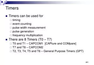
8051 Timers -- Basics. 8051 Timers “count up,” incrementing the Timer’s respective “count register” each time there is a triggering clock pulse. When the “count register” rolls over from all 1’s to all 0’s, a “Timer Flag” bit will be raised to indicate “Timer Overflow.”.


8051 Timers -- Basics
E N D
Presentation Transcript
8051 Timers -- Basics • 8051 Timers “count up,” incrementing the Timer’s respective “count register” each time there is a triggering clock pulse. • When the “count register” rolls over from all 1’s to all 0’s, a “Timer Flag” bit will be raised to indicate “Timer Overflow.” • Once the “Timer Flag” is set, the programmer must clear it before it can be set again (don’t forget this) • Once the “Timer Flag” is set, the Timer does not stop counting, thus the programmer will usually stop the Timer to handle the event(don’t forget this) • Once a Timer overflows, the programmer must reload the initial start value to begin counting up from(don’t forget this) • (e.g. Wait_Timer0: jnb TF0,Wait_Timer0 ;wait for T0 Flag • The “triggering clock pulse” that causes a timer’s count register to be incremented comes from one of two sources: • (1) The 8051’s external oscillator frequency÷12 • (2) A “1 0” transition event (i.e. falling edge) on an externalinput
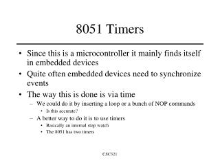
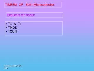
8051 Timers • 8051 has two Timers; • Timer 0 and Timer 1 are 16 bits wide • Both may be used as (1) timers or (2) event counters • A timer allows program to keep track of elapsed time What real-life app’s keep count?? • A counter allows program to count external events • Both are configured by Special Function Registers • TCON(88H) – Timer CONtrol(control/status for both T1 and T0) • TMOD(89H) – TimerMODe (mode for both T1 and T0) • TH0/TL0(8CH/8AH) – Timer 0 High/Low bytes • TH1/TL1(8DH/8BH) – Timer 1 High/Low bytes
Timer Registers - TMOD • TMOD (89H) (Timer Mode Control Register—not bit addressable) Bit Name Timer Comments 7 Gate 1 Gate Bit – Normally “0”; if “1” Timer1 only runs when INT1* = 1 6 C/T* 1 Counter/Timer select ( 0 = Timer / 1 = Counter) 5 M1 1 Timer Mode00: 13 bit timer(not used much) 4 M0 1 Select 01: 16 bit timer 10: 8 bit timer, auto-reload 3 Gate 0 (same) 2 C/T* 0 (same) 1 M1 0 (same) 0 M0 0 (same) 11: Split mode Overflow Flag Timer Clock Timer Clock M0 M3 TLx(8) THx(5) TFx TL1(8) TH1(8) Timer Clock M1 TLx(8) THx(8) TFx Overflow Flag Timer Clock TL0(8) TF0 Timer Clock M2 TLx(8) TFx FOSC 12 reload TH0(8) TF1 THx(8)
Timer Registers - TCON • TCON (88H) (Timer Control Register—bit addressable) Bit Name Address Comments 7 TF1 8Fh Timer1 overflow flag. Set by hardware on T1 overflow; clear by software or automatically cleared by hardware when 8051 vectors to “Timer ISR” 6 TR1 8Eh Timer1 run-control, set/cleared by software to turn Timer1 on/off 5 TF0 8Dh Timer0 overflow flag. Set by hardware on T0 overflow; clear by software or automatically cleared by hardware when 80512 vectors to “Timer ISR” 4 TR0 8Ch Timer0 run-control bit, set/cleared by software to turn Timer0 on/off 3 IE1 8Bh External Interrupt1 edge flag. Set by hardware when a falling edge is detected on INT1* input; clear by software or automatically cleared by hardware when 8051 vectors to “Timer ISR” 2 IT1 8Ah External Interrupt1 type control, set/cleared by software. (1=detect falling edge, 0=detect low-level) 1 IE0 89h External Interrupt0 edge flag 0 IT0 88h External Interrupt0 type control • Bits 7, 5, 3 and 1 are status flags, bits 6, 4, 2 and 0 are control bits • Bits 7, 6, 3 and 2 are for using Timer1 • Bits 5, 4, 1 and 0 are for using Timer0
Clocking Sources • C/T* bit in TMOD controls whether it is a timer or a counter F÷12 On-chip oscillator Divide By 12 F 1.0 MHz (1.0 uSec) 921.6 KHz (1.0851 uSec) 11.0592 MHz crystal 12.00 MHz crystal C/T*=0 C/T*= 1 Timer Clock T0 or T1 pin 0 is up 1 is down C/T* P3.4 = T0 P3.5 = T1 One machine cycle S1 S2 S3 S4 S5 S6 S1 S2 P1 P2 P1 P2 P1 P2 P1 P2 P1 P2 P1 P2 P1 P2 P1 Osc. • In countermode (C/T*=1) the external input (T0 or T1) is sampled in S5P2 of every machine cycle. Timer reg’s are incremented in response to 1-to-0 transition. Since it takes two machine cycles (2 us) to recognize a transition (10) , the maximum external frequency is 500 KHz (assuming 12MHz operation).
Calculating 8051 Timer Values to Load • When 8051 Timers are used in “Timer” mode, the incrementing period (Tinc) is 1/(F÷12) • Example 1: if F=12 MHz then Tinc = 1 µsec. • Example 2: if F=11.0592 MHz then Tinc = 1.0851 µsec. • Divide the desired delay time needed by Tinc to obtain # increments (Ninc) • Perform 65536 - Ninc (Dinc) • Convert Dinc to the 4-digit hexadecimal value in the form yyxx • Load TH with “yy” and TL with “xx”. TH yy, TL xx • Example: if F=12 MHz, find the Timer value to load to create a 50 ms delay • Ninc = 50E-3 / 1E-6 = 50,000 • Dinc = 65,536 – 50,000 = 15,536 • 15,536 0x3CB0; therefore yy=0x3C and xx=0xB0 • TH 0x3C; TL 0xB0
Minimum and Maximum 8051 Delays • Let’s assume the 8051 is operating at 12MHz so Timers can be incremented • at 1Mhz (once every µsec). • What are the minimum and maximum delays that we can create ? • Minimum delay is limited not by timer clock frequency but by software. • Example: Write a code segment to create a waveform with the shortest possible period: clr P2.0 ;square wave on P2.0 Quick_Loop:cpl P2.0 ;toggle for hi to lo sjmpQuick_Loop ; and lo to hi sequence What are the Frequency and duty cycle of this waveform? • Maximum delays using Timers are based upon the timer register size • 8-bit timer: max count is 0 to FFh, thus max overflow occurs after 256 increments • 16-bit timer: max count is 0 to FFFFh, thus max overflow occurs after 65536 increments • Maximum delay for 12MHz 8051 is 65536 µsec, or 65.5 msec • Maximum delay for 11.0592MHz 8051 is 65536*1.0851 µsec = 71.1 msec • As with software delay routines, we can have 16-bit timer sections embedded in software loops to create unlimited delays
Timer Diagram (disable Gate) Block Diagram of Timer 1 so that Timer1 is enabled to count When TR=1 and Gate = “0” these signals are always “1”
Timer Diagram (enable Gate) Block Diagram of Timer 1 Timer1 only counts When INT1* = 1 When TR=1 and Gate = “1” Timer1 will not count this signal is only “1” when INT1* is deasserted (i.e. “1”) this signal will be “0” when INT1* goes low (i.e. asserted)
TMOD Gate Bit for Pulse Measurement • Using the Gate Bit set (i.e. 1) in conjunction with inputs INTx allows the measuring of the duration of external signals (a.k.a pulse measurement) • In this example we measure duration of signal on INT0* • Program Timer 0 to Mode 1 (16-bit timer) • TH0/TL0 0000H • Gate 1 • TR0 1 • When INT0* goes HIGH the OR-Gate is high and the count begins in 1 MHz increments (assuming 12MHz oscillator) • When INT0* goes LOW the OR-Gate is low, counting will stop, and the count in TH0/TL0 is the number of microseconds that INT0* was asserted. • You can program the 8051 to generate an interrupt on the HIGH to LOW transition on INT0* which tells you when to read the count
8-Bit Auto-Reload (Mode 2) • This provides an 8-bit timer (Timers 0 or 1) that will automatically refresh with the initial count upon reaching the terminal count • THx is programmed with the base count • TLx is the timer that will get incremented and will set the TFx bit when TLx “overflows” Timer Clock TLx(8) TFx • When TFx bit is set, the contents of THx is automaticallycopied to TLx and the counting continues reload Mode 2 THx(8)
Sample Code • (thus T=1.0 msec = 1000 µsec) • Use Timer 0 • Assuming 12 MHz 8051, thus 1 usec increment rate • 1 KHz Square Wave Generation • Duty cycle of 50%, therefore 500 µsec low-time and 500 µsec high-time • 16-bit timer mode (delay longer than 256 µs so mode 2 can’t be used) • 65536 - 500 = 65036 = 0xFE0C • Thus, TH0 0xFE and TL0 0x0C • Will need to be “tuned” if an exact output frequency is required ORG 5800H mov TMOD,#00000001b ;16-bit timer0 mode Loop:mov TH0, #0FEh ;-500 (high byte) mov TL0, #0Ch ;-500 (low byte) setb TR0 ;start timer Wait:jnbTF0,Wait ;wait for overflow clr TR0 ;stop the timer clr TF0 ;clear timer overflow flag cpl P1.0 ;toggle port bit sjmpLoop ;repeat END