Download
1 / 96
990 likes | 1.29k Views
Power Transmission: Belts, Chains, Clutches, and Brakes . Power Transmission.

E N D
Power Transmission • In many machine designs, power must be transmitted from a driving source to the rest of the machine. The driving source may be an electric motor, engine, windmill, whatever … often, the energy must be transmitted to the rest of the machine to accomplish useful work. • We will talk about flexible elements used to transmit power, and the control of that power.
Belts and Chains • Flexible elements, which are economical alternatives to gears for transmitting rotary motion between shafts. Can be lighter, smaller, and as efficient as gears. • However, usually the life is more limited. • Bicycle “gears” (chain drive) versus automotive gears: efficient, lightweight, compact, vastly greater range of ratios.
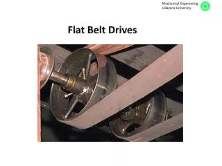
Types of Belts Common belts include flat, round, V, and timing belts. Flat belts can be very efficient, but require high tension levels, which require beefier parts. Round belts are similar, outstanding for non-parallel shafts. V belts are most common, as we will discuss. These belts all depend on friction between the belt and the pulley (or sheave). Most slip a few %.
Timing Belts • Toothed or synchronous belts don’t slip, and therefore transmit torque at a constant ratio: great for applications requiring precise timing, such as driving an automotive camshaft from the crankshaft. • Very efficient. More $ than other types of belts.
Flat, Round, and V Belts • Flat and round belts work very well. Flat belts must work under higher tension than V belts to transmit the same torque as V belts. Therefore they require more rigid shafts, larger bearings, and so on. • V belts create greater friction by wedging into the groove on the pulley or sheave. This greater friction = great torque capacity.
V Belt & Sheave Cross Section Wedging action along sides = high torque cap. The included angle 2 ranges between 34o and 40o.
Flat Belts vs. V Belts • Flat belt drives can have an efficiency close to 98%, about the same as a gear drive. • V belt drive efficiency varies between 70% and 96%, but they can transmit more power for a similar size. (Think of the wedged belt having to come un-wedged.) • In low power applications (most industrial uses), the cheaper installed cost wins vs. their greater efficiency: V belts are very common.
Flat Belt Drive Equations T = (F1 – F2)r hp = (F1 – F2)V/33,000 = Tn/63,000 speed ratio: n1/n2 = r2/r1 sin = (r2 – r1)/c contact angle (small) = – 2 cent. force in belt: Fc = (w/g)V2 F1 = Fc + [ /(-1)](T1/r1) = ef/sin (Where = 90o for a flat belt)
Chains • Compared to belts, chains can transmit more power for a given size, and can maintain more precise speed ratios. • Like belts, chains may suffer from a shorter life than a gear drive. Flexibility is limited by the link-length, which can cause a non-uniform output at high speeds.
Chains • Chain drives can be very efficient. Bicycle example; there are very few belt-drive bicycles. • The fact that the user controls the length (with master links) is a plus. However, the sprockets wear out much more frequently than does a belt sheave. Take your pick!
Chain Sizes (U.S.) • The “chain number” is nominally the roller-to-roller pitch in 1/80 inch increments. • Size 40 chain = ½” pitch ~ bike chain. • Size 80 chain = 1” pitch. • Size 120 chain = 1 ½” pitch.
Clutches & Brakes • Both use friction to control rotational power. • Clutches are used to couple & decouple rotating members; typically a power source from the rest of a machine. Auto example. • Brakes are used to dissipate rotational energy.
Friction Materials • Clutches and brakes depend on friction to operate. Typically one surface is metal, either steel or cast iron. The other surface is usually of a composite nature, for example soft metal particles embedded with reinforcing fibers in a bonding matrix. • Conflicting requirements of minimal wear, but acceptable f.
Single Plate Disc Clutch (for yoke shifter)
Hydraulically Actuated Multiple Plate Clutch, “Wet or Dry” What’s wrong with this picture?
“Wet” Clutches • Why on earth would an engineer design a clutch where the plates operate in an oil bath? Isn’t friction the idea? • Cooling, smooth operation (no ‘grabbing,’ and reduced wear, that’s why. • True that f is reduced and so sizes must be increased – but a worthwhile tradeoff.
Simple Band Brake Very similar to a belt drive; torque capacity is T = (F1 – F2)r
Differential Band Brake The friction force helps to apply the band: therefore it is “self-energizing.” Can become self-locking: Fa = (1/a)(cF2 – sF1)
Short-Shoe Drum Brakes If the shoe is short (less than 45o contact angle), a uniform pressure distribution may be assumed which simplifies the analysis in comparison to long-shoe brakes.
Self-Energizing & Self-Locking Brakes If the rotation is as shown, then Fa = (Fn/a)(b – fc). If b <= fc, then the brake is self-locking. Think of a door stop, that is a self-locking short shoe brake.
Long-Shoe Drum Brakes Cannot assume uniform pressure distribution, so the analysis is more involved.
Internal Long-Shoe Drum Brakes Formerly in wide automotive use; being replaced by caliper disc brakes, which offer better cooling capacity (and many other advantages). Brakes can dissipate enormous amounts of power.
The band brake shown has a power capacity of 40 kW at 600 rpm. Determine the belt tensions. Given: = 250, r = 250 mm, a = 500 mm, and f = 0.4.
Torque T = (9549 x kW)/n = (9549 x 40)/600 = 636.6 N-m F1 = F2e f, where is in radians, so F1 = F2e (.4)(4.363) = 5.727F2 T = (F1 – F2)r Or, T = (.25)(5.727F2 – F2) = 1.182F2
Therefore, F2 = 538.6 N, and, F1 = 3,085 N
Threads and Connections We will start off discussing the mechanics of screw threads. Next, power screws & threaded fasteners will be examined. Since threaded fasteners are often used to make connections, we will end with that topic.
The Inclined Plane Wrapped into a helix, this becomes one of the world’s great inventions. By inspection, a steeper angle gains you elevation more quickly, but the applied force must increase. W fN Q N
Helically-Inclined Planes Differential element of one thread transferring force to the mating thread. The helix or lead angle = the slope of the ramp, and is a critical design parameter. is the thread angle, and is another important parameter.
, , and f • On a screw thread, the helix angle controls the distance traveled per revolution and the force exerted. • , the thread angle, effects the friction force resisting motion. Sometimes friction is desirable (e.g., so that threads won’t loosen), and sometimes it is not. • f is the coefficient of friction, and plays an important role in all threads.
and , the helix angle, is given by tan = L/(dm) where, L = the lead or pitch (threads per unit length) dm = the mean dia. of the thread contact surface. As dm increases, decreases. , the thread angle, is determined by the design of the threads; not a function of L or dm.
Thread Friction Examples • Acme Threads • Bolt Threads • Pipe Threads
Power Screws Force F acts on moment arm a to produce a torque T. Tables show standard sizes of power screw threads. In this drawing, only the nut rotates.
Power Screw Thread Types Acme: in wide use, but less efficient. Square: most efficient, but hard to make. Modified Square: compromise.
Self-Locking of Power Screws Self locking is an important design feature for jacks. Occurs when the coefficient of thread friction is >= the tangent of the helix angle * the cosine of the thread angle: f >= cosntan
Power Screw Efficiency Note the wide range as a function of both f and .
Threaded Fasteners – Thread Forms Note that the crests & roots may be either flat or rounded
Threaded Fasteners: UNS & ISO • UNS = Unified National Standard. Threads are specified by the bolt or screw diameter (also called the major diameter)in inches, and the number of threads per inch. • ISO = International Standards Organization. Threads are specified by the major diameter in mm, and the pitch, or, number of mm per thread. • Generally UNS and ISO threads are NOT interchangeable. (3mm is close to 1/8”….)
Threaded Fasteners – UNS The specification is written in the format “Dia – threads/in – UNC or UNF – class and internal or external – RH or LH.” UNC = Unified National Coarse UNF = Unified National Fine Class ranges from 1 (cheap & inaccurate) to 3 (expensive & precise). Class 2 is common. A = external, B = internal
Threaded Fasteners – UNS RH = right hand threads, LH = left hand Example thus would be: ½ – 13 UNC – 2A – RH Notes: • “UNF” and “UNC” are redundant information. • For diameters less than ¼”, a numeric size is specified instead of the diameter. (000 – 14)
Threaded Fasteners – ISO Metric designations are a little simpler. Preceded by an “M,” then the diameter in mm, then the pitch (mm per thread, not threads per mm). There are also coarse and fine threads in the ISO system. Examples: M10 x 1.5 M10 x 1.25