Download
1 / 32
320 likes | 459 Views
This summary presents insights from a seminar on the TLEP (Twin Linear Electron-Positron collider) Accelerator, led by Frank Zimmermann of CERN. Highlighting collaborative efforts supported by the European Commission under the 7th Framework Programme, the seminar discussed technological advancements surrounding circular colliders and the requirements for future high-energy physics research. Key topics included infrastructure reuse, luminosity targets, beam lifetime limits, and the importance of top-up injection for maintaining high luminosity. This foundational work aims to pave the way for next-generation colliders.

E N D
A First Look at the TLEP Accelerator Frank Zimmermann, CERN-BE on behalf of the TLEP SG TH Seminar, 16 October 2013 • thanks to R. Aleksan, R. Assmann, M. Benedikt, A. Blondel, • Y. Cai, O. Dominguez, J. Ellis, B. Holzer, P. Janot, M. Koratzinos, • H. Maury Cuna, S. Myers, K. Ohmi, K. Oide, J. Osborne, • L. Rossi, J. Seeman, V. Telnov, R. Tomas, J. Wenninger, • S. White, U. Wienands, K. Yokoya, M. Zanetti, … Work supported by the European Commission under Capacities 7th Framework Programme, Grant Agreement 312453
circular colliders & storage rings … CESR BEPC LEP Tevatron LEP2 HERA DAFNE PEP-II KEKB BEPC-II LHC SuperKEKB (soon) 3rd generation light sources • since 1960 ~30 ring colliders successfully built & operated 1992ESRF, France (EU) 6 GeV ALS, US 1.5-1.9 GeV 1993 TLS, Taiwan 1.5 GeV 1994ELETTRA, Italy 2.4 GeV PLS, Korea 2 GeV MAX II, Sweden 1.5 GeV 1996APS, US 7 GeV LNLS, Brazil 1.35 GeV 1997 Spring-8, Japan 8 GeV 1998BESSY II, Germany 1.9 GeV 2000ANKA, Germany 2.5 GeV SLS, Switzerland 2.4 GeV 2004SPEAR3, US 3 GeV CLS, Canada 2.9 GeV 2006: SOLEIL, France 2.8 GeV DIAMOND,UK 3 GeV ASP, Australia 3 GeV MAX III, Sweden 700 MeV Indus-II, India 2.5 GeV 2008SSRF, China3.4 GeV 2009PETRA-III, Germany 6 GeV 2011ALBA, Spain 3 GeV • + many more e±storage-ring light sources (with ever smaller transverse emittance) well understood technology & typically exceeding design performance within a few years
LEP achievements integrated luminosity peak luminosity evenbetter at higher energy emittance ratio ex/ey R. Assmann Chamonix XI & APAC’01
TLEP design targets • c.m. energies: 240 GeV (ZH) + 91(Z), 160(WW), 350(), [+ 500 GeV (ZHH,H)?] • luminosities: L: several 1034 cm-2s-1/IP at ZH, >> 1035cm-2s-1/IP at the Z • polarization up to WW for ~100 keV energy calibration • extendibility – reusing tunnel + infrastructure for 100-TeVppcollider, 1st step in HEP long-term vision P. Janot et al, arxiv1308.6176
key constraints: in words … • SR power 100 MW ↔ wall plug power → beam current • limit on beam-beam tune shift: • extrapolated from LEP2 & KEKB & other colliders • #bunches ↔ luminosity, e-cloud, parasitic collisions • hor. emittanceex: bending radius r, optics (#magnets) • emittance ratio ey/ex: alignment, tuning, beam-beam • vertical b*y,: bunch length & optics • beam lifetime: • radiativeBhabha scattering (unavoidable) • beamstrahlung(design optimization)
… and in formulae … and in formulae SR radiation power limit beam-beam limit constrained by beamstrahlung to be reduced as much as possible!
lifetime limit: rad. Bhabha scattering beam lifetime at beam-beam limit: s for rad. Bhabha: help from theorists? → H. Burkhardt, R. Kleiss, EPAC1994 • LEP2: tbeam,LEP2~ 6 h (~30% suppression: s~0.21 barn) • TLEP with L~5x1034 cm−2s−1 at 4 IPs: • tbeam,TLEP~21 minutes, unavoidable
lifetime limit: beamstrahlung (BS) • synchrotron radiation in the strong field of opposing beam • make some e± lose large part of their energy • h: momentum acceptance • sx: horizontal beam size at IP Note: Many theoretical beamstrahlung studies in 1980’s. Example R. Blankenbecler, S.D. Drell , “A Quantum Treatment of Beamstrahlung,” Phys.Rev. D36 (1987) 277 & then be lost→ limited beam lifetime with V. Telnov, PRL 110 (2013) 114801 • mitigations: • (1) large momentum acceptance h • (2) flat beams [i.e. small ey & large bx*] • (3) fast replenishing →minimize ke=ey/ex, by~bx(ey/ex) & respect by≥sz
from LEP2 to TLEP-H • larger ring: higher energy or beam current • 4-5 x more SR power: 23 MW → 100 MW • a few times smaller emittanceat equal energy (r, cell length) • by* reduced by factor 50 - also requires smaller sz ~ by* (natural for larger ring) - steady-state BS energy spread ≤0.3% • top up injection to support short lifetime
TLEP: double ring with topping up A. Blondel short beam lifetime (~tLEP2/40) due to high luminosity supported by top-up injection (used at KEKB, PEP-II, SLS,…); top-up also avoids ramping & thermal transients, + eases tuning
top-up injection: schematic cycle beam current in collider (15 min. beam lifetime) 100% 99% almost constant current energy of accelerator ring 120 GeV injection into collider injection into accelerator 20 GeV acceleration time = 1.6 s (assuming SPS ramp rate) 10 s
top-up injection at PEP-II top-up performance at PEP-II/BaBar Before Top-Up After Top-Up J. Seeman J. Seeman average luminosity ≈ peak luminosity similar results from KEKB
TLEP Main Parameters energy = 91, 160, 240, 350 & 500 GeV c.m. circumference ~100 km total SR power ≤ 100 MW #IPs = 2 or 4 beam-beam tune shift / IP scaled from LEP luminosity / IP ~ 5x1034cm-2s-1 at the Higgs ~1000 x LEP2 top-up injection by* = 1 mm ~ sz
com-parison with LEP2
TLEP energy upgrade?
similar proposals around the world SLAC/LBNL design: 27 km TLEP: 80 or 100 km near Geneva LEP3: 27 km TLEP (LEP4): 80 km near Geneva SuperTRISTAN in Tsukuba: 40 (& 60 or 80 “TLEP”) km or HF in 27-km LHC tunnel (“LEP3”) Y. Cai, U. Wienands, A. Chao et al Mike Koratzinos et al K. Oide FNAL site filler, 16 km FNAL Snowmass proposal: 100 km “TLEP” & FNAL VLLC 233 km ring Chinese Higgs Factory CEPC + Chinese pp Collider 50 or 70 km P. Bhat, T. Sen et al Qing QIN et al
IR optics - momentum acceptance h with synchrotron motion & radiation (sawtooth) KEK design before optics correction KEK design after optics correction • IR optics w. up to h~2% acceptance ±1.1% ±1.3% K. Oide ±2.0% ±1.6% FNAL site filler SLAC/LBNL design Y. Cai T. Sen, E. Gianfelice-Wendt, Y. Alexahin
Emittances in Circular Colliders & Modern Light Sources Y. Funakoshi, KEK no problem achieving target emittances with top up injection TLEP (240) R. Bartolini, DIAMOND
b* history b* [m] year SPEAR PEP, BEPC, LEP PETRA TRISTAN DORIS CESR-c, PEP-II BEPC-II CESR DAFNE KEKB TLEP SuperKEKB IP beam size
SuperKEKB – aTLEP demonstrator beam commissioning will start in early 2015 • by*=300 mm (TLEP: 1 mm) • lifetime 5 min (TLEP: ~15min) • ey/ex=0.25% ! (TLEP: 0.2%) • off momentum acceptance (±1.5%, TLEP: ±2%) • e+ production rate (2.5x10¹²/s, TLEP: <1x10¹¹/s)
luminosity of e+e- colliders TLEP-Z S. Henderson TLEP-W TLEP-H TLEP-t
e+e- Higgs factories: luminosity ultimate precision at Z, WW, ZH ; sensitive to New Physics in multi-TeVrange & to SM closure → case for VHE-LHC ultimate energy reach up to 1 or 3 TeV ; direct searches for New Physics
TLEP technical systems BNL 5-cell 700 MHz cavity • SC RF at ~800 MHz as developed for ESS, BNL, CERN SPL • need 12 GeV/turn at 350 GeV • ~600 m of SC RF cavities @ 20 MV/m • LEP2 had 600 m at 7 MV/m • high power : ~200 kW / cavity in collider • power couplers similar to ESS – 700-800 MHz preferred • cryogenics system for the RF • like LHC cryo system (~ ½ LHC’s) • arc magnets • ~500-700 G at top energy, ~50 G at injection • similar to LHeC prototype magnets RF Coupler (ESS/SPL) • we could build it tomorrow! LHeC dipole w 0.35 mm laminations (BINP) • LHeC dipole withone-turn conductor& air cooled • interleaved laminations [1 mm iron, 2 mm plastic] • (CERN)
polarization LEP R. Assmann loss of polarization due to growing energy spread LEP observations + model predictions polarization scaling (energy spread!): LEP at 61 GeV → TLEP at 81 GeV TLEP optimized scenario TLEP U Wienands, April 2013 100 keVbeamenergy calibration byresonantdepolarization (using pilot bunches) aroundZpeak and W pair threshold: mZ~0.1 MeV, Z ~0.1 MeV, mW ~ 0.5 MeV r = 9000 m, C = 80 km lower energy spread, high polarization up to W threshold A. Blondel
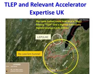
80-100 km tunnel in Geneva region J. Osborne, C. Waaijer, CERN, ARUP & GADZ, submitted to European Strategy Symposium 2012 TLEP/VHE-LHC
is 80-100 km too big? “Of course, it should not be the size of an accelerator, but its costs which must be minimized.” • Gustav-Adolf Voss, • builder of PETRA, • † 5. October 2013
FCC study - scope & structure Future Circular Colliders (FCC) - Conceptual Design Study & Cost Review for next European Strategy Update Infrastructure tunnels, surface buildings, transport (access roads), civil engineering, cooling ventilation, electricity, cryogenics, communication & IT, fabrication and installation processes, maintenance, environmental impact and monitoring, safety Hadron collider Optics and beam dynamics Functional specifications Performance specs Critical technical systems Related R+D programs HE-LHC comparison Operation concept Detector concept Physics requirements e+ e- collider Optics and beam dynamics Functional specifications Performance specs Critical technical systems Related R+D programs Injector (Booster) Operation concept Detector concept Physics requirements Hadron injectors Beam optics and dynamics Functional specs Performance specs Critical technical systems Operation concept e- p option: Physics, Integration, additional requirements two pillars: pp & e+e-; emphasis on ppmachine, driving infrastructure
possible long-term strategy TLEP (80-100 km, e+e-, up to ~350 GeV c.m.) PSB PS (0.6 km) LHC (26.7 km) SPS (6.9 km) HL-LHC VHE-LHC (pp, up to 100 TeVc.m.) & e± (120 GeV) – p (7, 16 & 50 TeV) collisions ([(V)HE-]TLHeC) ≥50 years of e+e-, pp, ep/A physics at highest energies
tentative long-term time line 1980 2000 2010 1990 2030 2020 2040 Design, R&D LHC Constr. Physics Proto. Design, R&D Constr. Physics HL-LHC Design, R&D TLEP Physics Constr. Design, R&D Constr. Physics VHE-LHC
synchroton-radiation: heat load TLEP has >10 times less SR heat load per meter than PEP-II or SPEAR! (though higher photon energy) N. Kurita, U. Wienands, SLAC SR heat per meter lower than for many operating rings