Download
1 / 5
50 likes | 177 Views
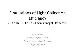
Simulations for Optimizations of Aerogel Testing. NORTH. HEIGHT. AEROCM. AEROL2. AEROL1. AEROW2. LENGTH. TOP. GUIDEW. WEST. EAST. BOTTOM. WIDTH. LGUIDE. AEROW1. GUIDEL. SOUTH. The Original Setup.

E N D
NORTH HEIGHT AEROCM AEROL2 AEROL1 AEROW2 LENGTH TOP GUIDEW WEST EAST BOTTOM WIDTH LGUIDE AEROW1 GUIDEL SOUTH The Original Setup The original setup allowed for the placement of an Aerogel panel inside of a single light box. PMTs could be place on any of the four sides of the Aerogel panel. It also allowed for a light guide between the edge of the Aerogel panel and the walls of the light box.
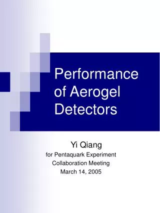
N WIDTH E W S Aerogel Box LENGTH < HIGHT > AEROCM BOTTOM 5” PMT Light Box Extension Box TOP < GUIDEL > The New Setup The new setup consists of a box containing Aerogel (1-10cm thick) connected to a light diffusion box. The light box is then connected to an extension, which diverts the light at a 90 degree angle into the PMT.
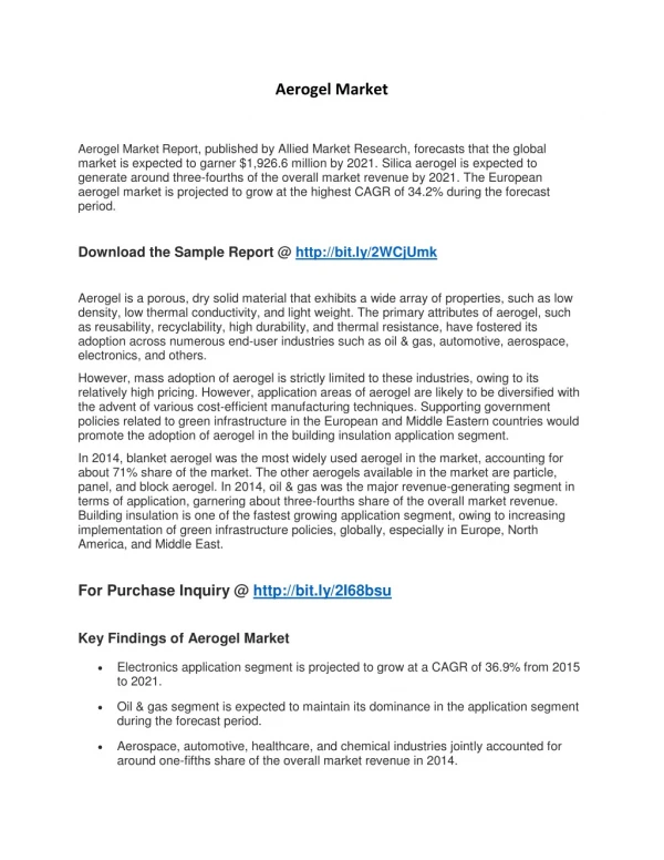
N Aerogel Light Box LENGTH < GUIDEW > W WIDTH BOTTOM E 5” PMT Extension Box S Second Light Box TOP < GUIDEL > Modifications Approximate that the Aerogel actually sits on the top of the light box (effectively ignore the dimensions of the Aerogel light box) Treat the light box and the extension box as a single, continuous box (we would then need to average the reflectivities of the two boxes to use a single value) *Create an option that allows the length of the extension box to be varied*
Status • Code has been manipulated to show when a photon enters the extension box • Variables have been created to allow for the implementation of the extension box • In the process of expanding the section of code that determines which wall the photon hits to account for the addition of the expansion box