Download
1 / 28
280 likes | 505 Views
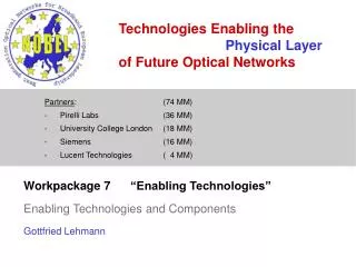
Technologies Enabling the Physical Layer of Future Optical Networks. Partners : (74 MM) Pirelli Labs (36 MM) University College London (18 MM) Siemens (16 MM) Lucent Technologies ( 4 MM). Workpackage 7 “Enabling Technologies†Enabling Technologies and Components Gottfried Lehmann.

E N D
Technologies Enabling the Physical Layer of Future Optical Networks • Partners: (74 MM) • Pirelli Labs (36 MM) • University College London (18 MM) • Siemens (16 MM) • Lucent Technologies ( 4 MM) Workpackage 7 “Enabling Technologies” Enabling Technologies and Components Gottfried Lehmann
Agenda • Introduction in WP7 objectives and activities • Overview on Technology Requirements • Summary
Main Objectives of WP7 Identification of key components and technologies for future networks • Identify existing technologies and components for cost-effective network architectures as specified from WP3-6. • Definition of requirements and desired characteristics of advanced components/subsystems for future core and metro networks • Evaluation and test of important components • Evaluation of monetary aspects of different technologies
O O O O X X X X C C C C OADM OADM WP7 – Main Building Blocks (Technology) for future optical networks
Short and Medium Term l -conversion Ÿ All-Optical packet Ÿ switching Optical buffering Ÿ Packet Synchronization Ÿ OPS ? WP7 – Network Evolution and Technological barriers Technological barriers l Static -switching Today Faster Optical Ÿ Switches New Control Plane Ÿ l Dynamic -switching 2005 / 2008 Edge nodes with Ÿ (e.g. ASON) electrical buffers New burst-capable Ÿ optical components (especially amplifiers) 2008 / 2012 OBS Ÿ OBS over l - switching Long and Extended Long Term Ÿ OPS over l - conversion 2015 / …?
WP7 – Enabling Technologies for Network Evolution Summary short term network scenario medium term network scenario long term…. Transmitter Tunable Lasers ........... -------- Fast Tunable Laser Advanced modulation formats (DPSK, Duobinary, etc.) Burst Mode Tx Transmission EDFA and Raman amplification under dynamic operation Tunable optical compensators (CD, PMD) Receiver Adaptive receivers - bit rate, format - Electrical Compensation of CD, PMD – FFE, DFE, MLSE - Adaptation to power, noise Tunable filters Burst mode receivers Switching ROADM Thermo-optical MEMS SOA Space Switches Reconfigurable Optical Cross Connects Tunable lambda Converter & AWG based OXC Contention resolution – Fibre delay lines, RAM Signal processing Forward Error Correction Optical Performance Monitoring All-optical Wavelength conversion Optical regeneration
More Tuneable LasersSummary of tuneable laser requirements Inventory/Backup Dynamic Networks OBS/OPS Remote Provisioning Restoration/ Rerouting short term medium term long term Wide tuneability Performances aligned with fixed sources Slow tuning Reduced switching time (msec) Increased performances Wavelength Stability Integration in pluggable modules Nanosecond tuning Wavelength Stability Requirements
More ROADMSummary of ROADM requirements Remote provisioning/ Reconfiguration Transparent mesh network Inventory savings Ease network planning Transparent rings interconnection medium term long term short term network scenario …. Tuning time: msecs Any-lambda-to-any-port A/D ports: up to 100% Node order >2 Tuning time: secs Full C-band operation A/D ports: 10%-100% Requirements Architecture & Connectivity Operation Minimize IL East/West separation Signal conditioning Hitless Improve cascadability Signal equalisation Optical monitoring
More Adaptive ReceiversSummary of requirements of tunable receivers CD tolerance at 10 Gb/s 40Gb/s applications Dynamic transparent networks Burst/Packet Networks short term medium term long term extended long term Electrical equalisers FEC Tuneable dispersion compensators Suitable modulation formats PMDC Enhanced FEC Adaptive equalisation and compensation Tolerant modulation formats Fast Dynamic range adaptation Burst Clock Recovery Fast adaptation to signal distortions “Burst Receiver” Requirements
More Optical Performance MonitorSummary of OPM requirements (I) individual wavelengths Meshed network Receiver control short term short term network scenario medium term medium term network scenario long term ... …. Power level detectionand tilt control Partly OSNR information Multi-channel operation Interaction with Control- or Management Plane Root cause analysis In-band OSNR detection Detection of further penaltiese.g. PMD Fast detection of important parameters Control of tunable compensators Requirements
More Optical Parameter Monitor Summary of OPM requirements (II) Dynamic Networks OBS / OPS medium term network scenario medium / long term long term network scenario (extended) long term …. CD, PMD, OSNR, cross-talk, power equalization and outage, wavelength monitoring Large monitoring range Multi-channel operation Low power consumption Bit rate independent Format independent Provide feedback for active compensation Compatible with burst/packet lengths Fast response time (sub ms/µs) Requirements Application
More -Conversion / All-optical Regeneration Summary of optical signal processing requirements Dynamically Switched Networks Burst Switched Networks Packet Switched Networks medium / long term (extended) long term Mitigation of distortions in reconfigurable end-to-end transparent lightpaths Wavelength conversion for contention resolution and wavelength routing Requirements Application Cascadability Large tolerance to input distortions Able to access all wavelengths 10-40Gb/s Operation Cascadability Large tolerance to input distortions 10-40Gb/s Operation
More Cost Analysis and Rating (short/medium term) Estimation for a Choice of Components and Technologies
Summary (on WP7 results) • Component- or subsystem requirements are established or collected (interaction with WPs3-6) • Requirements and possible realisation and network scenario timelines are “synchronised” (interaction with WP1) • Variety of solutions for the technologies required are discussed • Promising solutions are studied in more detail by • Experiments (for short and medium term, if available within the project) • Theoretical study (for medium and long term) • All results are documented in the deliverables D20 and D34 • Lesson learnt: Interaction with other WPs worked well (same persons in different WPs) – but: technology assessment should be performed within the WP which requires the information WPs5-7 are merged in NOBEL phase 2
Thank you for your attention!
Back Tuneable LasersToday • Integration into 10Gb/s transponders • Full C-band tuning • Butterfly package • Low power consumption and simple electronic control • Several product/vendors on the market • Performances generally in line with requirements for short term network scenario • 10-20 mW optical output power • 35 nm tuneability • 50 GHz grid operation • Switching times range from few milliseconds to some seconds Main technologies
Central Timing control Burst timing control Lock. point IRear IGain IPhase IFront ITEC Optical Signal Electrical Signal Gain Front Rear Phase SOA Laser Peltier cooler output SG-DBR Dif. Amp. Output 2. Locker Activated 3. W’length locked LDC LDC LDC LDC TEC LDC LDC 4 3 TIA PD 1 Prop. cont. PI control output 2 Integrator output Locking circuit timing control Diff. Output 1. Laser Switch Amp 1. Laser Switch Proportional control output 25µs 1 second Integrator PD TIA Back Burst Tunable LasersWavelength-locked burst mode transmitter • Blanking (15dB) achieved by modulation of SOA section >35dB maybe achieved by operating SOA in reverse bias • Fast wavelength locking control loop provides feedback for fine tuning of laser phase section • Stability <1GHz and locking time around 2ms limited by bandwidth of laser drivers Action of wavelength locking control loop over short (25µs) and long (1 sec) burst lengths
Back ROADMROADMs based on Mux/demux and switches mux/demux + 2x2 switch mux/demux + NxN switch Single lambda access No East/West separation in standard configurations Not easily scalable to high channel counts 32 channels ROADM: - mature PLC platforms - improved performances (low IL and PDL) - high integration (mux/demux, VOA, monitor) - East/West separation (separated components) • Power consumption and dimensions reduced with: • - Heat insulating grooves • Higher index contrast • Polymer-based switches • - Alternative switch arrangements Asymmetric 24x8 switch (introduces a degree of blocking) with East/West separation Lucent [OFC2005 OTuD2] JDS [OFC2005 OThN5] 8x8 ROADM Dupont [PR 2003]
Back ROADMROADMs based on WB and WSS Wavelength Blocker Wavelength Selective Switch East/West separation Suitable for high channels count Reduced spectral narrowing Pay-as-you-grow, with off-ring upgrades Suitable for meshed networks Higher upfront cost Complex/expensive for ‘colorless’ 100% demux Low loss (<6 dB), high extinction (40 dB), 50/100 GHz Liquid Crystals or MEMS-based technologies Several proposals on the market • Hybrid PLC stack and MEMS mirror array: • 1x3 WSS • 40 chs demux • Diffractive grating and MEMS: • flat-top, no dispersion penalty • challenging opto-mechanical design Xtellus WB9000 Lucent [ECOC2005 Th3.6.4] Silicon Light Machine SLM3000 JDSU [OFC2005 OWB5]
Back Tuneable Dispersion Compensators Chirped Fiber Bragg Grating (CFBG) Mature technology available for 10 Gb/s and 40 Gb/s GDR and tuning speed are main limitations Integrated all-pass filters (ring resonators, etalon) Ring resonators: - Implemented in PLC - Thermal tuning (msecs) - Lab demos reported Tunable Gires-Tournois etalons: - Thermally tuned (seconds) - Prototypes have been demonstrated Tunable Lattice filters FIR filters implemented in PLC Thermal tuning (msecs) • Main adaptation schemes • BER monitor (accurate, 1-100 msec) or eye monitor (trade sensitivity and speed) • Spectral analysis (modulation format dependant, fast)
Back PMD Compensation 10G NRZ improvement of 4.7 ps mean DGD, at OSNR penalty of 2 dB 40G DPSK Improvement of 4.5 ps mean DGD, at an OSNR penalty of 2 dB (fixed delay= 12.5 ps)
Back Burst Receivers • Burst Mode Receivers require: • Fast locking time <128 bits (12.8ns @10Gb/s) • High Dynamic Range >-18dBm – 0dBm • Low Penalty <1dB • Demonstrations • 10 dB Dynamic range, locked in 30 ns with a power penalty of 2 dB at 12.5 Gb/s. Uses ac-coupled receivers • 25dB Dynamic range, 2dB penalty for 10Gb/s DPSK packets. Uses optical limiting amplifiers (LOAs) Rotem et al IEEE Transactions on Communications May 2005 Su et al IEEE Photonic Technology Letters Jan 2004
Back Optical Performance Monitoring • For end-to-end optical transparent paths quality information is required to be able to identify the root cause in failure case • Requirements: • Fast measurement • Multi-channel operation • Low power operation • Data rate and modulation format transparency • Low cost compared to lab equipment Classification of different OPM types
Test measurement 1: polarised ASE ASE signal minor problem OSA 22 3.5 ARGOS (20GHz) 3.0 20 PDL / dB 2.5 18 2.0 16 PDL equivalent/ dB OSNR / dB 1.5 14 1.0 12 0.5 10 0.0 10 12 14 16 18 20 22 OSNR (reference) / dB ASE || signal big problem 20 3.5 19.5 3.0 19 2.5 18.5 2.0 PDL equivalent/ dB 18 OSNR / dB 1.5 17.5 1.0 OSA 17 ARGOS (20GHz) 0.5 16.5 PDL / dB 16 0.0 16.0 16.5 17.0 17.5 18.0 18.5 19.0 19.5 20.0 OSNR (reference) / dB Back OPM evaluation “Polarisation Nulling” Assumption: - Signal is polarised - Noise is unpolarised Polarisation: - Maximum signal signal + ASE - Minimum signal ASE + In band OSNR measurement - Sensitive to Polarisation Effects Test measurement 2: PMD sensitivity except offset of 1 dB, good agreement Siemens [Nobel D34]
AWG AWG AWG Main Line Low speed Optical Filter |x|2 I G (t) Io A/D SSB |x|2 Comp. 90o Δφ (CD) |x|2 Q EAM Back Burst OPM and Impairment Compensation • Method based on RF spectrum analysis • Single Side Band Filter • Electro-optical mixing with optical modulator (EAM) for down conversion • Experimental results • Range of +312ps/nm • Measurement accuracy of • 50ps/nm RMS error using MZM • 20ps/nm using EAMs • Advantages • Monitors: Channel power, CD • Range suitable for 40Gbit/s systems (+312ps/nm) • Fast response time (sub ms) • Insensitive to first order PMD (filter shape dependent) • Robust to OSNR degradation • 35ps/nm RMS error for OSNR varying from 40dB to 22dB (simulation) • Potentially cheap (multi-channel operation) • limitationsCooperation with WP5 • Bit rate dependent Test of Virtual Imaged Phased Array • Format dependent (VIPA) confirms above study
18 16 14 12 Q 10 8 6 4 0 5000 10000 15000 20000 Transmission Distance (km) Back Optical Regeneration and -Conversion Q M N 10Gb/s RZ Tx 3R Rx 63 km SMF DCF WithoutRegeneration • Optical regeneration is used to correct for signal impairments in that will arise in reconfigurable transparent optical networks. • These results demonstrate the performance that is required when multiple optical regenerators are cascaded in a single lightpath. • Specifically both the signal Q and ER must be maintained at each regenerator IncreasingRegeneratorSpacing
Back Cost Estimation of Components and Technology Concepts (1)
Back Cost Estimation of Components and Technology Concepts (2)