Download
1 / 45
460 likes | 587 Views
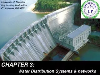
WATER DISTRIBUTION NETWORKS. CE 370. Distribution Network. Water distribution systems include mains storage reservoir booster pumping stations (if needed) fire hydrants service lines. PIPING NETWORKS.

E N D
WATER DISTRIBUTION NETWORKS CE 370
Distribution Network Water distribution systems include • mains • storage reservoir • booster pumping stations (if needed) • fire hydrants • service lines
Arterial mains or feeders: are pipelines of larger size that are connected to the transmission lines that supply the water for distribution. • All major areas must be served by a feeder loop and in duplicate, if possible. • Two moderately sized lines, which are few blocks apart, are preferred to be one main. • Parallel feeders are cross-connected at interval of one mile, with valving, for isolation in emergency cases. • Distribution lines are connected to arterial loops to form GRIDIRON SYSTEM which services fire hydrants and domestic and commercial consumers.
The gridiron system, as shown in the following Figure, is the best arrangement for distributing water because: • all arterial and secondary mains are interconnected • dead-ends are eliminated • water is circulated
At grid intersections, no more than one branch, preferably none, should be without a valve. • Feeder mains are placed in every second or third street in one direction and every fourth to eighth street in the other. • Distribution in intermediate streets should not be less than 6 inches (150 mm) in diameter. • Dead-end system, as shown in the Figure, should be avoided in new area and can be corrected in existing systems by proper looping.
Water stagnation at dead-ends may develop tastes and odors, to prevent this, dead-ends may require frequent flushing. • Pressure in systems with large elevation differences should preferably in the range of 50 to 100 psi (340 to 690 kPa) under average flow conditions. Since a pressure difference of 50 psi (340 kPa) is equivalent to an elevation of 115 ft (34 m), the desirable elevation change between the high and low points should be limited to this value.
Service Connections A typical service installation consists of a pipe from the distribution main to a turnoff valve located near the property line, as shown in the following Figure. A special tapping machine is used to insert the corporation stop while the main is in service under pressure. Water meters are installed inside or outside the property, as shown in the following Figure. The estimated rate for a typical house having two bathrooms, full laundry, kitchen, and one or two house bibbs is 15 gpm. A pressure of 15 psi is usually adequate to operate any fixture, with the exception of lawn sprinkler.
KINDS OF PIPE In water distribution system, the following pipes are used: • ductile iron • plastic • concrete • steel • copper (for house connections)
Pipe Materials Must Have The Following Properties • Adequate tensile and bending strength to withstand external loads (from trench backfill, earth movement caused by freezing, thawing, or unstable soils) • high bursting strength to withstand internal water pressure • ability to resist impact loads during transportation, handling, installation • smooth non-corrosive interior surface for minimum resistance of water flow • an exterior unaffected by aggressive soil and groundwater • material that can be provided with tight joints and easy to tap for making connections.
Ductile Iron Pipes Are noted for long life, toughness, imperviousness, and ease of tapping as well as withstand internal pressure and external loads. This kind of pipes is stronger, tougher, and more elastic than cast iron. Iron pipes are available in sizes between 2 and 48 inches in diameter (50 to 1200 mm). The selection of pipe thickness depends on: • internal pressure • external load • allowance for corrosion • design factor for safety
Plastic Pipes • They are not subject to corrosion or deterioration by chemical or biological activities. • They are smooth, minimizing friction losses in water flow. • Commonly manufactured sizes are 4 to 12 inches (100 to 300 mm) with internal pressure of 100, 150, and 200 psi.
Concrete Pipes • Three types of reinforced concrete pipes are used for pressure conduits. • They have the advantage of durability, water tightness, and low maintenance costs. • They are applicable in larger sizes (16 to 144 inches).
Steel Pipes • Used in transmission lines. • They are of high strength, able to yield without breaking, resisting shocks. • Protection against corrosion is necessary.
Pumps • high-lift pumps deliver water from treatment to distribution system • booster pumps to deliver water to elevated points in the distribution area • common pumps used in high service: • vertical-turbine pumps • horizontal split-case centrifugal pumps • why? • They have good efficiency • They have the capability to deliver water at high discharge heads • This type of pumps operates at a range of capacities from design flow to shutoff without excessive loss of discharge pressure or efficiency.
Distribution storage can be provided by: • elevated tanks • standpipes • underground basins • covered reservoir
Elevated Tanks • have the advantage of that the pressure is derived from holding water that is higher than the surrounding terrain • can be made from steel (50,000 to 3 mil gallons)
Ground-level Standpipes or Reservoirs • provided when gravity water pressure is not necessary or when booster pumps are used • Steel standpipes are available in sizes of up to 5 mil gallons • The term standpipe is applicable where the height of the tank exceeds its diameter • If the diameter is greater than the height then it is a reservoir • Concrete reservoirs can be constructed above or below the ground
Storage basins need to be covered to: • reduce the possibility of pollution • reduce the possibility of deterioration of the interior surface Exposure to the atmosphere will result in: • airborne contamination • algal growth due to penetration of sun light • freezing of water surface in cold climates The choice between elevated and ground storage depends on: • topography • size of community • reliability of water supply • economic aspects In general elevated tanks are more economical and are recommended for small water systems. Reservoirs and booster pumping facilities are usually less expensive in large system.
Functions of distribution storage: • permit continuous treatment of water • permit continuous uniform pumping rates of water into the distribution system • store water in advance of actual needs at one or more locations Advantages of distribution storage: • water demands are nearly equal at source, treatment, transmission, and distribution • flow pressure of the system is stabilized throughout the service area • reserve supplies are available for emergency cases such as fire fighting.
To determine storage needed, the following must be considered: • volume used to meet variations in demand • amount related to emergency reserves The storage needed to meet supply and demand is determined from hourly variation on the day of maximum consumption. Reserve capacity for fire fighting is determined from required fire flow and duration. The location, capacity and elevation of a storage tank depend on water demands and their variations throughout the day in different parts of the system. It is more advantageous to provide several smaller storage units in different locations than an equivalent capacity at a central site. By doing so: • smaller distribution pipes are required • more uniform water pressures are established throughout the system At normal consumption rates, some stored water should be used each day to allow recirculation. At peak consumption rates, the fire reserve should not be used.
Valves are used in • Treatment plants • Pumping stations • Piping system • Storage reservoirs Valve function • control magnitude and direction of flow How they function • they have movable parts that extend into the pipeline for opening and closing the interior passage.
Common types of valves • slide • rotary • globe • swing Less common valves • sphere • diaphragm • sleeve • vertical lift disk
Valves are also classified by operating purpose • shutoff • altitude Valves can be classified by function • by-pass • flow control These two classifications have nothing to do with the valve type. Movable parts of valves are operated by: • screw • gear • water pressure
Screw stems are common in: • gate valve • globe valve • needle valve Gears are common in: • butterfly valve • gate valve • globe valve • ball valve Water pressure control is common in: • swing gate valve • automatic globe valve
Shutoff Valves These valves are used to stop the flow of water through a pipeline in order to sectionalize the network in emergency cases. At pipe junctions, minimum of three valves have to be installed. Shutoff valve must be installed on the pipe connecting the fire hydrant to the distribution system for maintenance. Treatment plants and pumping stations have to be equipped with shutoff valves at the inlet, outlet, and by-pass lines to allow repair of pumps Shutoff valves are: • gate valves • rotary butterfly valves (installed in large diameter valves)
Check Valves A check valve is a semiautomatic valve that allows water flow in one direction only. They open under the influence of water pressure. They are installed in discharge lines of centrifugal pumps to prevent backflow when the pump is off.
Small Pressure-Reducing and Pilot Valves These valves reduce high inlet pressure to a predetermined lower outlet pressure. They are used to: • protect house plumbing from excessive main pressure • control the action of large automatic valves that are operated by water pressure.
Automatic Control Valves These valves use the water pressure to open or close. The valves are used as: • pressure-reducing valves • altitude valves • controlled check valves • surge relief valves • shutoff valves
Pressure-Reducing Valves They are automatic valves operated to maintain a predetermined outlet pressure against a higher inlet pressure. These valves are used on mains connecting separate water networks located on two different elevations. The outlet pressure is held constant even if the inlet pressure varies.
Altitude Valves They are used to automatically control the flow into and out of an elevated tank or a standpipe in order to maintain desired water-level elevations. The valve is designed as a double-acting sequence valve. The valve automatically closes when the tank is full to prevent overflow, and when the pressure on the distribution side of the valve is less than that on the tank side, the valve opens allowing water to leave the tank.
Solenoid Pilot Valves A solenoid is a coil of wire wound in a helix so that when electric current flows through the wire a magnetic field is established within the helix. The force created by the magnetic field is enough to close or open the valve.
Air- Release Valves Air enters a pipe network from: • a pump drawing air into the suction pipe • leaking joints • dissolved gases being released from the water Air pockets can increase the resistance to the flow of water, and they can be entrapped in: • high points of distribution system • valves and fittings • discharge lines from pumps Theses valves are installed to release trapped air.
BACKFLOW PREVENTERS The water in distribution systems must be protected against contamination from backflow of water through customer service lines and other system outlets. Backflow of toxic chemicals and wastewater containing pathogens is of greatest concern. Back siphonage is water backflow that results from: • reduced pressure in the supply piping • repair of a water main at an elevation lower than the service point • a break in a pipe • reduced pressure from the suction side of booster pumps
There are four kinds of mechanical backflow preventers: • atmospheric-vacuum breaker • pressure-vacuum breaker • double check valve • reduced-pressure-principle Selection of the kind of backflow preventer depends on: • type of installation • hazards involved if backflow occurs
Vacuum and Pressure-Vacuum Breakers Atmospheric-vacuum breakers are installed on: • lawn sprinklers • overhead pipe of a water filling station Pressure-vacuum breakers are installed on: • where low inlet water connections are not subject to back pressure Double Check Valves are used to: • protect against backflow of nontoxic substances in direct water connections subject to backflow • protect against backflow of nontoxic and toxic substances in direct water connections not subject to backflow Reduced-Pressure-Principle Backflow Preventers are installed on: • service connections to industries • service connections to chemical plants • service connections to hospitals • service connections to irrigation systems
Fire hydrants are used to: • fight fires • clean streets • flush out water mains They are installed behind the curb line, usually 2 ft, to protect it from overhanging vehicles. The pipe connection a fire hydrant to the distribution main is normally not less than 6 inches (150 mm) in diameter and includes a gate valve for hydrant isolation.