E1 Automatic Protection Switching Solution (1+1 E1 Redundancy Switch)
170 likes | 207 Views
Learn about the features and benefits of E1 Automatic Protection Switching solution for telecom transmission systems. Ensure network reliability and resilience with this solution.

E1 Automatic Protection Switching Solution (1+1 E1 Redundancy Switch)
E N D
Presentation Transcript
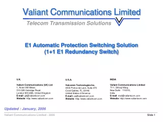
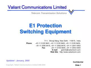
Valiant Communications Limited Telecom Transmission Solutions E1 Automatic Protection Switching Solution (1+1 E1 Redundancy Switch) U.K. Valiant Communications (UK) Ltd 1, Acton Hill Mews, 310-328 Uxbridge Road, London W3 9QN, United Kingdom E-mail: gb@valiantcom.com Website: http://www.valiantcom.com INDIA Valiant Communications Limited71/1, Shivaji Marg, New Delhi - 110015, India E-mail: mail@valiantcom.com Website: http://www.valiantcom.com U.S.A. Valcomm Technologies Inc. 4000 Ponce de Leon, Suite 470Coral Gables, FL 33146United States of America E-mail: us@valiantcom.com Website: http://www.valiantcom.com Updated : January, 2006
E1 Automatic Protection Switching Solution Basic Theory of Operation • E1 Redundancy Switch is designed to provide 1+1 redundancy support for two typical E1 links case scenarios: • An independent point-to-point E1 link between two "E1 USER PORTS" • TWO groups of E1 links connected via a higher order multiplexer link. • Since each SWITCH Card supports one E1 link, up to 16 E1 links, can be supported by an E1 Redundancy Switch Shelf. Two Systems are required for implementation of the 1+1 redundancy switch solution. • One system must house Switch Cards configured as "MASTER" for connection at one end of the E1 links (say the near end). • The other system must house Switch Cards configured as "SLAVE" for connection at the other end of the E1 links (say the far end).
E1 Automatic Protection Switching Solution Features & Highlights • Provides 1+1 E1 redundancy link (active+standby) between any two complementing transmission mediums. • Provides 1+1 E1 redundancy support to higher order multiplexers eg. E2,E3. System configuration & management interface through "CLI" text based commands. • Transport A-bis Interface or E1’s. • Provide 1 + 1 Protection Routing / Path between BSC and BTS. Provide following interfaces at BSC / BTS Over E1 links: • E1 / A-bis Interface. • 10BaseT Ethernet Bridge. • RS232 Async Serial (for site monitoring). • NO / NC Relay / Alarm Extensions (Extend alarms Originating on dry relay contacts). • Optional - 128 ms Echo - Cancellation and VQE features at BSC. • Maximize mobile operator service availability and network resiliency through VCL-MegaConnect-Jr. Path - Protection enabled facility.
E1 Automatic Protection Switching Solution Features & Highlights • These ensure that mission critical voice, data, control and management traffic are properly supported and maintained even during T1 / E1 backhaul facility outages.When the working link fails, the protection link becomes active. • During normal Operation, VCL-MegaConnect-Jr sends duplicate traffic across both the working and dedicated protection E1 / T1 facilities while continuously maintaining the performance of both links to determine which link shall be utilized. • Through the comprehensive digital access cross-connect and remote management capabilities integrated within VCL-MegaConnect-Jr, backhaul T1 / E1 facilities can be optimally groomed to reduce both Capital Expenditure and improve Network reliability. • In the event of a failed or degraded T1 / E1 link, the traffic is automatically transferred from the previously working link to the duplicate protection link in accordance with the pre determined operating parameter programmed by the network operator.
E1 Automatic Protection Switching Solution Features & Highlights • During normal Operation, VCL-MegaConnect-Jr APS passes independently traffic across both the working and protection E1 / T1 facilities while continuously maintaining the performance of both links to determine which to utilize for critical traffic. • Traffic Protection. • Alternate Facility Advantages. • Service Differentiation Agreements. • Increased Network Reliability Resilience. • Media and Path Diversity. • Remote Management.
E1 Automatic Protection Switching Solution Benefits Applications • Customer Relation • Competitive • Service Level • Back-haul Network • Technology Migration • 1) User Programmable 1+1 Protection Parameters: • Loss of Signal • Loss of Frame • Loss of Multi-Frame • AIS • Excessive CRC4 Violation • 2) Critical Links / Critical Time-Slots • Providing 1+1 alternate paths between any two Transmission medium (active+standby). e.g:- • Fiber / Fiber. • Radio / Fiber. • Radio / HDSL • Fiber / HDSL etc.
E1 Automatic Protection Switching Solution Applications Diagram 1+1 REDUNDANT RING CONFIGURATION APPLICATIONS # 1
E1 Automatic Protection Switching Solution Applications Diagram TYPICAL STAR CONFIGURATION APPLICATIONS # 2
E1 Automatic Protection Switching Solution Applications Diagram Two User selectable MegaConnect optionsare available for reliable networks operation APPLICATIONS # 3
E1 Automatic Protection Switching Solution Applications Diagram MegaConnect (With Path Protection Switching) Normal Operation APPLICATIONS # 4
E1 Automatic Protection Switching Solution Applications Diagram MegaConnect (With Path Protection Switching) Normal Operation APPLICATIONS # 5
E1 Automatic Protection Switching Solution Applications Diagram MegaConnect (With Path Protection Switching) Working Link Fault APPLICATIONS # 6
E1 Automatic Protection Switching Solution Technical Specifications E1 Interface Number of Interfaces 16 Conformity (Electrical) G.703 Frame Structure As per ITU (CCITT) G.704 Bit Rate 2048 Kbps ± 50 ppm Code HDB3 Nominal Impedance 120 W balanced Peak Voltage of a mark For 120 W Balanced interface 3.0 V ± 0.3 V Peak Voltage of a space for 120 W Balanced interface 0 V ± 0.3 V Nominal Pulse Width 244 ns Pulse Mask as per ITU (CCITT) Rec. G.703 Output Jitter < 0.05 UI (in the frequency range of 20Hz to 100 KHz) Permissible Attenuation 6 dB at 1 MHz Return Loss at: 51.2 KHz to 102.4 KHz > 12dB 102.4 KHz to 2048KHz > 18dB 2048KHz to 3072 KHz > 14dB Jitter Tolerance As per ITU (CCITT) G.823 Loss and recovery of frame alignment As per clause 3 of ITU (CCITT) G.732
E1 Automatic Protection Switching Solution Technical Specifications Time-slot selection: ANY-TO-ANY through an internal, best byte, non-blocking TSI Switch. Clock: Internal (Stratum3 level) Loop-Timed External 75 Ohms - 2.048 Mhz - 1.544 Mhz Management and Control: Serial Management Port (RS232) - COM Port 10/100 BaseT for Remote Management over a LAN. 10/100 BaseT Telnet over a TCP-IP Network. Command Language: Command Line Interface (english text commands)
E1 Automatic Protection Switching Solution Technical Specifications Specification and Regulation Compliance Meets CE requirements Complies with FCC, Part 68 and Part 15 subpart A specifications Safety - UL 1459 Issue 2 Alarm Contact Closures 1 Alarm Relay, Type - Form "C" relay, Temperature Operating 00C to 500C Humidity 5% to 95% Non-Condensing Input Voltage Voltage -48 VDC (Range from -40 VDC to -60 VDC) Current 0.104 Amp at -48 VDC
E1 Automatic Protection Switching Solution Valiant’s Products • Digital Access Cross Connects - E1 / T1 , E3, DS3, 10/100 BaseT Ethernet • Groomers (Hi-Z Non-intrusive Hi-Impedance Monitoring) • 1+1 APS (Automatic Protection Switching) • Echo Canceller & Voice Quality Enhancement Solutions - E1, T1, DS3 and STM-1 • E1 Drop-Insert (Add-Drop) Voice and Data Multiplexers • E1, T1, E3, DS3, Ethernet Converters • STM-1 Add Drop Multiplexer with Ethernet • GSM Gateways - E1/T1 • E1 PRI ISDN (Euro ISDN) Q.931 Multiplexers • Channel Banks • E2 (4 E1), 2/34 Mbps PDH Multiplexer, 34 Mbps OLTE • Remote Site Monitoring Equipment
E1 Automatic Protection Switching Solution Thank you for your attention For more details visit us at our Website at http://www.valiantcom.com U.K. Valiant Communications (UK) Ltd 1, Acton Hill Mews, 310-328 Uxbridge Road, London W3 9QN, United Kingdom E-mail: gb@valiantcom.com Website: http://www.valiantcom.com INDIA Valiant Communications Limited71/1, Shivaji Marg, New Delhi - 110015, India E-mail: mail@valiantcom.com Website: http://www.valiantcom.com U.S.A. Valcomm Technologies Inc. 4000 Ponce de Leon, Suite 470Coral Gables, FL 33146United States of America E-mail: us@valiantcom.com Website: http://www.valiantcom.com

![Height [ ft ] E1: (3,6) E2: (4,7) E3: (5,8)](https://cdn1.slideserve.com/3559167/slide1-dt.jpg)