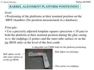
BARREL ALIGNMENT PLATFORM POSITIONING
90 likes | 207 Views
This document outlines the methods for positioning MDT chamber platforms accurately during assembly. The primary goal is to achieve nominal platform positioning through the use of precisely adjusted templates and control tools. Essential techniques include utilizing a calibrated tube and straight rulers for measurement, as well as leveraging optical control tools for angle verification during tube layer assembly. The process also emphasizes the importance of absolute calibration on a granite table before assembly. Detailed imaging techniques and tools for monitoring platform orientations are also described.

BARREL ALIGNMENT PLATFORM POSITIONING
E N D
Presentation Transcript
Dubna 06/2000 C. Guyot (Saclay) BARREL ALIGNMENT PLATFORM POSITIONING • Goal: • Positioning of the platforms at their nominal position on the • MDT chambers (No position measurement in a database). • Principle: • Use a precisely adjusted template squares (precision < 10 mm) to • hold the platform at their nominal position during the glue curing • w.r.t. the endplugs (2 points) and the outer tube surface or on the jig (BOS only) at the level of the first comb. 6 adjustable (on CMM) balls for the platform positioning Half sphere on end plugs Half sphere on the tube outer surface or on the jig (BOS) Flat surface on endplugs
Top view Praxial platform positioning tools: Bottom view
Positioning in x of the template tools on the tube layer: Ruler with straigthness < 100 mm Tube with calibrated length (+- 50 mm) Platform screwed on the positioning square
lens The optical control tools • Goal: • Check the platform orientation (angles) during the tube layer assembly • ( Reminder: The platforms are glued on the first layer) • Register on a database the values of the angles measured after only one • tube layer glued (i.e. right after the platform gluing) and the angles mesured at the • end of the multilayer assembly. For the module 0 assembly, register the values after each • tube layer assembly (Not possible on BIL due to the stiff back geometry). Principle: 4 tools (towers) carrying 2 cameras and 2 LEDs looking at each neighbour CMOS image sensor 2 leds f~ 80 mm (except for BIS transverse: 60 mm) Plateform angle ~ (X/Y(pixel) - X0/Y0) * pixel_size / f Average led spot coordinate From the calibration on the granite table
y14 x14 x12 y12 y34 y43 x43 x41 x32 y41 y32 Measured platform angles Image sensor axis (pixel direction) Xch Ych y23 x23 Tower 2 Tower 1 x21 y21 Signal side HV side x34 Tower 4 Tower 3 Zch Rotation of platform 1 around Xch axis: qX = (X14-X014)/f Rotation of platform 1 around Ych axis: qY = - (Y12-Y012)/f = - (Y14-Y014)/f Rotation of platform 1 around Zch axis: qZ = - (X12-X012)/f Rotation of platform 2 around Xch axis: qX = (X23-X023)/f Rotation of platform 2 around Ych axis: qY = (Y21-Y021)/f = (Y23-Y023)/f Rotation of platform 2 around Zch axis: qZ = (X21-X021)/f
Control tool calibration Longitudinal lines : Distance adjusted to +- 2mm Precision wedges z Calibrates rotations around z and y axis x
Distance adjusted to +- 2mm Precision wedges Square ( 90 degrees +- 1 mrad) x Calibrates rotations around x axis only z Control tool calibration Transverse lines :
Saclay will supply each MDT lab (barrel) with a set of 4 template squares and a set of 4 control tools (with cables to the RASMUX). • Each lab will have to provide: • - A length calibrated tube • - A straight ruler of length ~ chamber width - square width • The absolute calibration of the control tools will have to done • on a granite table prior to the module 0 assembly. • This calibration requires a precision side on the granite table or • (better) a precision wedge. If the assembly table on side does not allow such a calibration (no room or no precise side face), this calibration will be done at Saclay (hoping that the image sensor does not move during the transport).