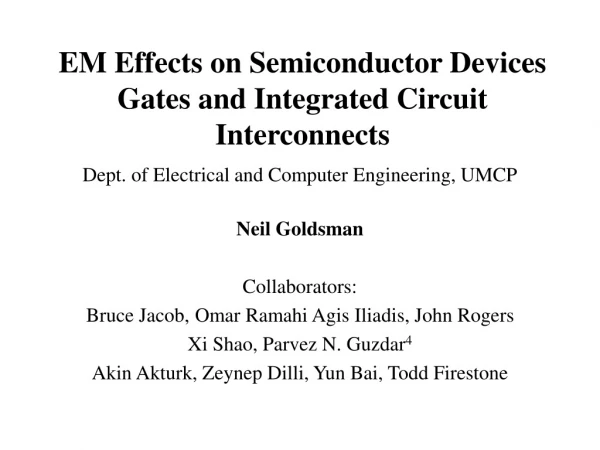
Semiconductor circuit templates
Semiconductor circuit templates. This presentation is partially animated. Only use the control panel at the bottom of screen to review what you have seen. When using your mouse, make sure you click only when it is within the light blue frame that surrounds each slide.


Semiconductor circuit templates
E N D
Presentation Transcript
Semiconductor circuit templates This presentation is partially animated. Only use the control panel at the bottom of screen to review what you have seen. When using your mouse, make sure you click only when it is within the light blue frame that surrounds each slide.
Pre-presentation Self Assessment Activity Your comfort level with your response to the following three question assessment tool should indicate if the presentation that follows will increase you knowledge base on the topic outlined by the questions in this tool.
(1000 ohms) V R ref (5 volts) 1 + - v out Pre-presentation Self Assessment Activity 1. Draw the I-V characteristic curve for the following diode circuit. 2. Design a NPN transistor circuit that will monitor a variable resistor sensor. 3. Design a NPN transistor circuit that will control a electromagnetic relay.
Semiconductor circuit templates (click on button for the corresponding topic of interest) 1) Diode circuits ( 1 pn junction) (a) Voltage regulators (b) Current - voltage curves 2) NPN transistor (2 pn junctions) (a) Digital flip-flop output circuit (b) Linear output amplifier circuit 3) Silicon-controlled rectifier (3 pn junctions) (a) 16 channel decoder (b) 8 channel decoder
Click anywhere in button surface to return to topic selection page
pn junction n p volt meter anode 0 0 0 0 p pn junction + + current current meter meter cathode n volt meter np junctions as diode template No current flow This diode is reverse biased Current flow This diode is forward biased
R R 1 1 + 0.6 volt drop (unregulated input voltage ) - (Regulated output voltage supply) + v v v out out out + + + + - 2 Silicon diodes in series np junctions as diode template voltage regulator voltage regulator = 2 (0.6 volts) + - (Regulated output voltage supply) anode cathode 2 Silicon diodes in series
R R 1 1 + - + + + + + + - - - - - - (unregulated input voltage ) v v v out out v 1 np junctions as diode template voltage regulator voltage “dropper” (unregulated input voltage ) = - 0.6 volts (Regulated output voltage supply) out 1 3 Silicon diodes in series
voltage “dropper” R R 1 1 + - + + + + - - - (unregulated input voltage ) = - 0.6 volts (unregulated input voltage ) - v out 1 (Regulated output voltage supply) + v v out out - 2 Silicon diodes in series v 1 np junctions as diode template voltage regulator These two silicon diode circuits will provide the same regulated output voltage value if the unregulated input supply voltage is the same for both.
(1000 ohms) R (5 volts) 1 + - current v out Voltage np junctions as diode template Finding the current that flows through the diode isn’t quite so simple. Value of Vout is easy to find. For silicon diode Vdrop is= 0.6 volts. One way to find this current value is to create a load line diagram. Vout = 0V + Vdrop (1) Use a model to plot the i vs v response for the diode. (2) Plot the conductance value for R1 on the same graph.
(1000 ohms) R (5 volts) 1 + - 600 500 current current v 400 out (A) 300 200 1 2 3 4 5 6 Volt Voltage np junctions as diode template Finding the current that flows through the diode isn’t quite so simple. Value of Vout is easy to find. For silicon diode Vout is= 0.6 volts. One way to find this current value is to create a load line diagram. (1) Use a model to plot the i vs v response for the diode. (2) Plot the conductance value for R1 on the same graph.
(1000 ohms) Value of Vout is easy to find. R For silicon diode Vout is= 0.6 volts. (5 volts) 1 + - (q)(v) 600 (k)(T) 500 -12 current v X10 i i 400 amps 1.0 out s s (A) -23 300 X 10 J/K 1.38 200 -19 X 10 1.60 C 1 2 3 4 5 6 Volt np junctions as diode template (1) Use a model to plot the i vs. v response for the diode. Model for diode current flow. e i = + Typical is value = k (Boltsman’s constant)= q (charge on an electron)=
(1000 ohms) Value of Vout is easy to find. R For silicon diode Vout is= 0.6 volts. (5 volts) 1 (q) (k) (T) + - 600 (1V, 510 amps) 500 - 2 - 8 - 8 - 2 -13 2 2 -13 current +1.0 +5.0 +5.1 +1.0 +5.1 +2.2 +5.0 +2.2 -13 -13 X 10 X 10 X 10 X 10 X 10 X 10 X 10 X 10 v i i 400 out s s -10 -10 -13 -13 (A) -10 -10 300 200 np junctions as diode template (1) Use a model to plot the i vs. v response for the diode. (v) (+.3) (+.7) (+.5) (-.5) (+1) (-2) e i + = v i -2 -0.5 +0.3 +0.5 +0.7 +1.0 1 2 3 4 5 6 Volt
(1000 ohms) Value of Vout is easy to find. R For silicon diode Vout is= 0.6 volts. (v) (+.3) (+.7) (5 volts) (+.5) (-.5) 1 (+1) (-2) (q) (k) (T) + - 600 500 v 2 current +5.1 X 10 v R i i 400 out s s i = i = i = (A) r r r +5.0 Volts 300 3 X 10 Ohms 1.0 200 -3 X 10 Amperes 5.0 1 2 3 4 5 6 Volt np junctions as diode template (2) Plot the conductance value for R1 on the same graph. (v) diode model for current e + = i d The diode model for predicting current is a different equation than the resistor model for predicting current. The resistor model for predicting current is (of course) Ohm’s law.
(1000 ohms) Value of Vout is easy to find. R For silicon diode Vout is= 0.6 volts. (v) (+.3) (+.7) (5 volts) (+.5) (-.5) 1 (+1) (-2) (q) (k) (T) + - 600 A A 500 current v i i 400 out s s i = i = i = (A) r r r 300 200 -3 -3 1 2 3 4 5 6 0.0 5.0 X 10 X 10 Volt np junctions as diode template (2) Plot the conductance value for R1 on the same graph. (v) diode model for current e + = i d The load line is now defined by the following two points. ( , ) 0v ( , ) 5v v R Current axis needs to be expanded to plot these two points. +5.0 Volts 3 X 10 Ohms 1.0 -3 X 10 Amperes 5.0
(1000 ohms) Value of Vout is easy to find. R For silicon diode Vout is= 0.6 volts. (v) (+.3) (+.7) (5 volts) (+.5) (-.5) 1 (+1) (-2) (q) (k) (T) + - ( , ) 600 6 0v A A 500 5 ( , ) 5v current v i i 400 4 out s s (A) 300 3 200 2 -3 -3 0.0 5.0 X 10 X 10 np junctions as diode template (2) Plot the conductance value for R1 on the same graph. (v) diode model for current e + = i d The load line is now defined by the following two points. current (mA) 1 1 2 2 3 3 4 4 5 5 6 6 Volts Volts
(1000 ohms) Value of Vout is easy to find. R For silicon diode Vout is= 0.6 volts. (v) (+.3) (+.7) (5 volts) (+.5) (-.5) 1 (+1) (-2) (q) (k) (T) + - 600 6 A 500 5 2 current +5.1 X 10 v i i 400 4 out s s (A) 300 3 200 2 -3 -3 0.0 5.0 X 10 X 10 np junctions as diode template (2) Plot the conductance value for R1 on the same graph. (v) diode model for current e + = i d The load line is now defined by the following two points. ( , ) 0v ( , ) 5v A current The absolute value of the slope of this line is the conductance of the resistor. (mA) 1 1 2 2 3 3 4 4 5 5 6 6 Volts Volts
(1000 ohms) R (5 volts) 1 + - m 600 6 A 500 5 5v current current v 400 4 out (A) (mA) 300 3 200 2 -3 -3 1 1 2 2 3 3 4 4 5 5 6 6 1.0 5.0 X 10 X 10 Volts Volts np junctions as diode template (2) Plot the conductance value for R1 on the same graph. Value of Vout is easy to find. For silicon diode Vout is= 0.6 volts. mhos = = The absolute value of the slope of this line is the conductance of the resistor. (The inverse of the slope is the resistance value for the resistor. )
Click anywhere in button surface to return to topic selection page
pn junction p current meter n anode volt meter collector current cathode meter This diode is forward biased base + emitter n + p pn junctions 0 0 0 0 0 0 current + meter n + + + volt volt meter meter This transistor is conduction NPN transistor circuit template 1 pn junction 2 pn junctions
0 + + + + volt meter NPN transistor circuit template output signal Voltage, Vd, here varies as variable resistor knob is turned. n Input control signal p pn junctions n emitter Low resistance value
When gets high enough, the light will turn on. v d If v gets higher, the light will become brighter. d 0 + + + + volt meter NPN transistor circuit template output signal Voltage, Vd, here varies as variable resistor knob is turned. n Input control signal p pn junctions High resistance value n emitter Low resistance value Medium resistance value
When gets high enough, the light will turn on. v d If v gets higher, the light will become brighter. d 0 + + + + volt meter NPN transistor circuit template output signal Voltage, Vd, here varies as variable resistor knob is turned. n Input control signal p pn junctions High resistance value If the input signal and the output signal are “grounded” at the same potential the circuit is know as a common-emitter circuit. n emitter Variable Resistor This transistor is connected in a common-emitter mode
When gets high enough, the light will turn on. v d + - R R 2 1 Voltage here, , v d goes up as the variable resistance value goes up. = + v 0 v R 0 v R v d Voltage across the variable resistor v = R NPN transistor circuit template output signal volt meter n input signal p n Variable Resistor E Many sensors are designed to provide a variable resistance output signal. This transistor is connected in a common-emitter mode
+ - R 1 0 v v in in NPN transistor circuit template At high voltage value, light is ON. high value At low voltage value, light is OFF. output signal volt meter Low value time n input signal p n the voltage across these two terminals = E This transistor is connected in a common-emitter circuit
+ - R 1 0 v v in in NPN transistor circuit template At high voltage value, light is OFF. high value At low voltage value, light is ON. volt meter Low value time n p n the voltage across these two terminals E This transistor is connected in a common-emitter circuit
+ - R 1 0 v v in in NPN transistor circuit template high voltage value high value volt meter low voltage value Low value time n p n the voltage across these two terminals E This transistor is connected in a common-emitter circuit
+ - R 1 0 v v in in NPN transistor circuit template high voltage value high value volt meter low voltage value Low value time n p n the voltage across these two terminals E This transistor is connected in a common-emitter circuit Example of a digital circuit - Flip-flop Output
+ - R R R 3 1 2 = + v 0 v 2 0 v v d d v in = v R R R (v ) 2 2 3 2 T + NPN transistor circuit template This light get brighter as input signal is linearly increased. There is a voltage at the orange node because of the voltage divider circuit element highlighted in blue. volt meter n Voltage divider output set so p transistor is just barely conducting. This light get dimmer as input signal is linearly increased. n This input signal is varied linearly to brighten/dim the lights. E This transistor is connected in a common-emitter circuit Example of a linear output circuit
V V V V ref ref + + current meter n n p p R R R sensor sensor Pull up n n E E v v b b NPN transistor circuit template Single pole double throw contacts to FCE power circuit 0 Reference voltage often not used. Reference voltage often not used. + R Pull up Template for monitor circuit Template for FCE circuit Output circuit to monitor resistive sensor Output circuit to activate relay
Click anywhere in button surface to return to topic selection page
anode gate cathode Silicon-controlled rectifier (SCR) Circuit Template
pn junction p current anode n meter + volt cathode meter collector meter This diode is forward biased current base emitter + meter n current pn junctions + p + N.O. anode n 0 0 0 0 0 0 0 0 0 + + A volt volt meter meter + gate p cathode This transistor is conduction n pn junctions + p + n + G K volt volt N.C. meter meter NPN transistor circuit template 1 pn junction 2 pn junctions 3 pn junctions
0 0 0 + + + + volt meter volt volt meter meter Silicon-controlled rectifier (SCR) Circuit Template ON push button Mouse click over ON push button to turn light ON N.O. anode A p gate cathode n pn junctions p OFF push button n G K N.C. Mouse click over OFF push button to turn light OFF silicon-controlled rectifier (SCR) circuit
0 0 0 + + + + volt meter volt volt meter meter Silicon-controlled rectifier (SCR) Circuit Template ON push button Mouse click over ON push button to turn light ON N.O. anode A Do it again and watch for all the things that happen. p gate cathode n pn junctions p OFF push button n G K N.C. Mouse click over OFF push button to turn light OFF silicon-controlled rectifier (SCR) circuit
0 0 0 + + + + volt meter volt volt meter meter Silicon-controlled rectifier (SCR) Circuit Template ON push button Mouse click over ON push button to turn light ON N.O. anode A Do you know why the volt meter needle goes up when the light goes off? p gate cathode Do it one more time. n pn junctions p OFF push button n G K N.C. Mouse click over OFF push button to turn light OFF silicon-controlled rectifier (SCR) circuit
(1000 ohms) R (v) (+.3) (+.7) (5 volts) (+.5) (-.5) 1 (+1) (-2) (q) (v) diode model for current (k) (T) + e + = i d - 600 6 ( , ) A 500 5 0v current current v i i 400 4 ( , ) out 5v A s s (A) (mA) 300 3 200 2 -3 -3 1 1 2 2 3 3 4 4 5 5 6 6 0.0 5.0 X 10 X 10 Volts Volts Post Presentation Self Assessment Activity 1. Draw the I-V characteristic curve for the following diode circuit.
V V ref + current meter n 0 Reference voltage often not used. p R sensor n E v b R Pull up Template for monitor circuit Post Presentation Self Assessment Activity 2. Design a NPN transistor circuit that will monitor a variable resistor sensor.
V V ref + to FCE power circuit Single pole double throw contacts Reference voltage often not used. n + p R R Pull up sensor n E v b Template for FCE circuit Output circuit to activate relay Post Presentation Self Assessment Activity 3. Design a NPN transistor circuit that will control a electromagnetic relay.