Download
1 / 24
520 likes | 4.45k Views
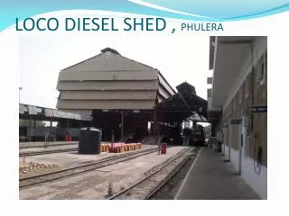
LOCO DIESEL SHED , PHULERA. About Indian Railways . Indian Railways has one of the largest & busiest rail networks in the world. It comes under the Ministry of Railways. It is the world’s largest commercial employer, with more than 105 million employees.

E N D
About Indian Railways • Indian Railways has one of the largest & busiest rail networks in the world. • It comes under the Ministry of Railways. • It is the world’s largest commercial employer, with more than 105 million employees. • The fleet of includes over 200,000 wagons, 50,000 coaches, 8,000 locomotives. • It also owns locomotives & coaches production facilities. • Indian Railways transporting over 20 million passengers. • Indian Railways are divided into 16 zones. & each zones is made up of a certain no. of divisions. There are 67 divisions. • The total length of the track used by Indian Railways is about 108,805 KM (67,608miles.) • About 50% of the total track KM is Diesel . • It also operates the Kolkata, Delhi metro.
WHAT IS DIESEL SHED • Diesel locomotive shed is an industrial – technical setup, where repair & maintenance works of diesel of diesel locomotives is carried out, so as keep loco working properly. • It contributes to increase the operational life of diesel locomotives • Minimize the line failure • The technical manpower of a shed also increases the efficiency of the loco. • Diesel shed usually has -; • Berths & plate for loco maintenance • Pits for under frame maintenance. • Heavy cranes, lifting jacks. • Fuel storage & lube oil storage, water treatment plant & testing labs etc. • Sub-assembly overhauling 7 repairing sections. • Machine shop & welding facilities.
SHED INFRASTRUCTURE SHED AREA ----------------------------------------------------------- 2261 sq.m . M.G SETELITE SHED----------------------------------------------- 1965- 1997. M.G HOME SHED---------------------------------------------------- FROM 1997 HOLDINGS ------------------------------------------------------------- 64. SHEDULES------------------------------------------------------------FOUR(TI1,TI2,M3,M9 ) STAFF CADER----------------------------------------------------------- 100 BEARTHING SPACE---------------------------------------------- 9 LOCO SHEDULE PIT 2 LOCO LOAD PIT MANUFACTURER----------------------------------------------------- ALCO/ DLW
THREE GENERAL CLASS OF LOCOMOTIVES Freight locomotive – For designed with slower speed, acceleration and have capacity to pull heavier load as compared to another. Ex. (WDG2, WDM4) Passenger locomotive-- For designed with high speed, fast acceleration & light loads. Ex. (WDP2, YDP4) Shunting locomotive-- For designed with slower speed, low HP and suitable for shunting purpose onl. Ex. (WDS4, WDS6)
CLASSIFICATION OF LOCOS • The first digit [gauge] • W= Broad Gauge • Y= Meter Gauge • Z= Narrow Gauge WDM3 • The second digit [power] • D= Diesel • C= DC traction • A= AC traction • CA= Dual-power AC/DC traction • B= Battery electric (rare) YDM3 • The third digit [load] • M= Mixed Traffic • P= Passenger • G= Goods • U= Multiple Unit ( EMU/ DEMU) ZDM3 • R= Railcar
How to start LOCO • Compression ignition engine • Firing order - 1,4,2,6,3,5 • Cycle of operations – suction, compression, power, exhaust
LOCO Specification YDM4 • Engine Model:- YDM4 • Engine Company:- ALCO • No. of Cylinder:- 6 • Cylinder Arrangement:- Inline • Cylinder Shape:- I shape • Engine BHP:- 1200 • Max. Weight:- 72 tone • Traction HP:- 1200HP • Gross HP:- 1280HP • Starting Speed: 100-150 r.p.m • Compression Ratio:- 12:1 • Full Speed:- 400-1100 r.p.m • Max. Speed:- 1200 r.p.m • Fuel Tank Capacity:- 3000 lit. • Wheel Arrangement:- co-co • Radiator Fan:- 41HP • Firing order is:- 1-4-2-6-3-5 • Dia. Of Wheel:- 965 mm • Compressor:- 1100 r.p.m • Battery:- Series Compound Shunt
SIX MAIN COMPONENTS OF ENGINE NOSE – It consists head light, sand box, resistance grid. DRIVER’s CAB – It consists long hood, short hood, control stand, air brake control stand, booster air pressure , indicating lube oil, pressure gauges, mechanical control & electrical speedometer and load meter. MAIN GENERATOR COMPARTMENT – It consists traction motor, excitation generator, auxiliary generator, front traction motor blower and housed in this compartment. ENGINE ROOM - It consists after cooler, turbocharger governor, fuel injection pump, fuel oil filters, lube oil filters, water pump, extension shaft, expressorspline coupling. EXPRESSOR COMPARTMENT – It produces a vacuum compressed air which is used for braking purpose, pump for hydraulic governor fuel booster pump & fuel booster pump motor are also kept. RADIATOR - Radiator fan, radiator panel, lube oil, right angle gear box, driving radiator fan, eddy current clutch which converts right angle gear box to diesel engine’s extension shaft.
ARRANGEMENT OF WHEELS IN THE LOCO • Wheels are first arranged into bogies. • It provides greater flexibility. • They are represented in two blocks separated by (-) sign. • This type of bogies are called CO-CO.
Function of components • Main Generator The diesel engine drives the main generator which provides the power to move the train. The alternator generates DC electricity which is used to provide power for the traction motors mounted on the trucks (bogies). • Auxiliary Generator This provides DC power for lighting, heating, air conditioning, dining facilities etc. on the train. • Motor Blower Motor blower provides air which is blown over the traction motors to keep them cool during periods of heavy work. • Air Intakes The air for cooling the locomotive's motors is drawn in from outside the locomotive. It has to be filtered to remove dust and other impurities
Batteries The diesel engine needs a battery to start it and to provide electrical power for lights. • Traction Motor Traction motors are provided on the axles to give the final drive. These motors were traditionally DC • Fuel Tank The fuel tank is normally under the loco frame and will have a capacity of 3000 lts. • Air Reservoirs Air reservoirs containing compressed air at high pressure are required for the train braking and some other systems on the locomotive. These are often mounted next to the fuel tank under the floor of the locomotive. • Drive Shaft The main output from the diesel engine is transmitted by the drive shaft to the generators at one end and the radiator fans and compressor at the other end. • Radiator and Radiator Fan Water is distributes around the engine block to keep the temperature within the most efficient range for the engine.
Air brake • Air Brake System (Loco Brake System) • SA-9 Valve : for loco brakes only • Release position :-running loco is in released position • Application position :- stopped pressure of 3.5kg/cm2 • Vacuum Brake System:- • A-9 Valve : for loco & train brake system • 1. Release position: - pressure to 5.0kg/cm2of MR. vacuum is about 55-60 cm. • 2. Minimum position:- pressure in brake pipe= 4.5 kg/cm2, vacuum =50-55 cm • 3. Service application:- Brake pipe pressure = 3.5 kg/cm2 , Vacuum =25-30 cm • 4. Over reduction:- Brake pipe pressure = 2.5 kg/cm2,Vacuum =20 cm • 5. Emergency:- Brake pipe pressure = 0.0kg/cm2, engine is in idle condition
EXPRESSOR • Expresser is made with combination of EXhauter + comPRESSOR. • It is located at free end of the engine block and driven through the extension shaft attached to the engine crank shaft. • Exhauster suck air from train pipe to create required amount of vacuum to brake system. • There are 6 cylinder are arranged in a W type, 2 cylinder in vertical, 4 in V shaped.
Turbo Supercharger • It is used increase the amount of air pushed into cylinder. • Pressure of air is 3-6 kg/cm2 • It gives a 50% increase in engine power. • Advantage is that it gives more power with no increase in fuel cost because it uses exhaust gas as driving power. • It also increase the air pressure, better ignition & efficiency. • CAUSES OF TURBO CHARGER • Intermediate casing, turbine casing, nozzle failure.
Failure Analysis • Ultra sonic test • In ultrasonic testing very short ultrasonic pulse – waves with center frequencies ranging from 0.1 – 15 MHz. • US testing is performed on steel ,metals and alloy. • It is a form of non destructive testing. • Zyglo test • Zyglo test is a of non destructive testing • It is quick & accurate process for locating surface flaws such as shrinkage cracks, fatigue cracks, grinding cracks etc. • Zyglo test is performed on metals & non metals materials like Al, Mg, Cu, brass, bronze, sintered carbide, non – magnetic alloys, ceramics, plastic & glass.
Schedule Examination Minor Schedule • Trip -1 & Trip -1 • Fuel oil, lube oil& filter are checked. • Expressor discharge valve. • Record oil level in the axle caps for suspension bearing. • Turbo super charger is checked. • Under frame are checked. Major Schedule • Run engine; check operation of air system safety valves & expressor crank case lube oil pressure. • Stop engine; carry out dry run operational test, check FIP timing & uniformity of rack setting & correct if necessary. • Engine crankcase cover:- remove crankcase cover and check for any foreign material, renew gasket. • Clean strainer & filters, replace paper elements. • Compressor air & vacuum system:- check, clean and recondition rings, intake strainers, & inlet, exhaust valve, lube oil relief valve. Drain, clean & refill crankcase. • Roller bearing axle boxes. Check for loose bolts, lose of grease. sign of overheating. Remove covers,. Carry out ultrasonic test of axles. • Renew airflow indicator valve.
SPECIAL PLANT • To provide pollution free environment, an ETP is installed. • Various effluents emitted from diesel shed are passed through the plant. • Pollution free water is collected & Water is used for non drinking purposes – gardening & washing of the locomotives.