KKM8 cascade manager
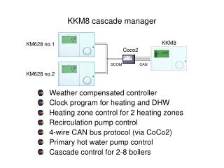
KKM8. KM628 no.1. Coco2. SCOM. CAN. KM628 no.2. KKM8 cascade manager. Weather compensated controller Clock program for heating and DHW Heating zone control for 2 heating zones Recirculation pump control 4-wire CAN bus protocol (via CoCo2)

KKM8 cascade manager
E N D
Presentation Transcript
KKM8 KM628 no.1 Coco2 SCOM CAN KM628 no.2 KKM8 cascade manager Weather compensated controller Clock program for heating and DHW Heating zone control for 2 heating zones Recirculation pump control 4-wire CAN bus protocol (via CoCo2) Primary hot water pump control Cascade control for 2-8 boilers
Commissioning level KKM8 (2) *1 03 if circuit is a DHW circuit *2 Program the nominal output for each boiler at module 1 (no boiler -> 0kW!!!)
Menu KKM8 Advanced explanation
Expert parameters (1) Expert Installation: Code number Password entry EntryCode number (adjustment) Password adjustment 0000Bus ID 1 Address heating zone 1 01Bus ID 2 Address heating zone 2 02AF supply Outside sensor voltage 01Bus term Bus resistance built in 00EBus supply EBus supply for devices connected to EBus 01Time master To switch time on other controllers 00Max T-coll Maximum header temperature 85Min T-coll Minimum header temperature 40Max T-HS2 Maximum temperature heat source 2 (n.a.) 85Min T-HS2 Minimum temperature heat source 2 (n.a.) 40V-curve Voltage curve selection 00Curve 11-U1 Curve 11, voltage point 1 4,0Curve 11-U2 Curve 11, voltage point 2 0,1Curve 11-T1 Curve 11, temp point 1 20Curve 11-T2 Curve 11, temp point 2 90Curve 11-UA Curve 11, voltage switch off point (summer) 5,0Hysteresis Hysteresis for switch off 5 See next page for continuation
Expert parameters (2) Expert Installation: Found moduls Number of boilers detected displayOutput/stage Boiler output programming !!!!!New config Start automatic search for boilers 00Min mod casc Min modulation output for cascade 00HW-Boiler Number of boilers for hot water production 00Contr deviat Display of header temperature deviation displayDes output Required system output in % displayBlock time Remaining blocking time before next stage displayMax T-modul Maximum boiler temperature 90Dyn upward Control dynamic for modulating up 100Dyn downward Control dynamic for modulating down 100Reset time I-share of temperature controller 50Modulat max Switch on capacity for next boiler 80Modulat min Switch off capacity for last boiler 30Min mod HS Min modulation degree for all boilers 0Mod level HW Modulation level for hot water boiler(s) 80Sequence 1 Entry of boiler sequence for sequence 1 12345678Sequence 2 Entry of boiler sequence for sequence 2 87654321 See next page for continuation
Expert parameters (3) Expert Installation: Sequence change Selection of sequence mode: 01 01 = Only boiler sequence 1 02 = Only boiler sequence 2 03 = Time controlled change between sequence 1 and 2 04 = 1/3 <-> 2/3 cascade sequence 05 = Rotating boiler sequence 06 = Boiler sequence by automatic sorting via hoursSeq SW time Time to sequence change 200Lock time Delay time before switching next boiler 00Hys burner 2 Hysteresis for 2nd stage of burner (n.a.) 2HS Coolfct Cooling function when boiler temp is too hot 00T-HS Cool Boiler temp at which cooling function starts 80Heatsource1 Primary heat generator type 06HS1 bus Bus connection type of heat generator 01Heatsource2 Secondary heat generator type 00Storage HS2 Heat accumulator type for heat source 2 00Buffer Heat buffer storage type 00Screed Activation of screed drying program 00Screed progr Entering of screed program for programming --Return
Expert parameters (4) Expert Hot water: DHW Relief Charge pump blocking if temp is too low 01Parallel Parallel running heating and hot water 0100 = Hot water priority 01 = Hot water partial priority 02 = Pump parallel running excl. direct zone 03 = Pump parallel running incl. direct zoneT-boiler DHW Temperature excess for hot water production 20Hyst DHW Hysteresis for hot water production 5DHW Followup Run-down time 0Therm input Selection device for DHW-temp reading 0 00 = Hot water sensor 01 = Hot water thermostatWall hung Boiler setpoint = actual temp + temp excess 00Load through Boiler loading with extra sensor 00Return
Expert parameters (5) Expert Heating circuit I/II: HC Function Heating circuit function 0000 = Standard heating circuit 01 = Control to fixed flow temperatures 02 = Swimming pool control 03 = Hot water circuit 04 = Return flow temperature increase via mixer motorPump mode Heating circuit and pump operation mode 0000 = Standard circulation pump control 01 = Pumps switching with limits (see user-area) 02 = pumps switching with heating program (no summer off!!!) 03 = Continous operation (24/7)Mixer open Mixer dynamics when opening 18*1Mixer close Mixer dynamics when closing 12*2*1 Mixer opens without interruption when Tactual = Tdesired – 18K *2 Mixer closes without interruption when Tactual = Tdesired + 12K See next page for continuation
Expert parameters (6) Expert Heating circuit I/II: Max T-flow Maximum flow temperature 80Min T-flow Minimum flow temperature (!!!) 10Frost prot Frost protection on outside temperature 0Out-temp-del Outside temperature delay 0:00Slope offset Heat slope offset (heat loss compensation) 5B-heat sink Maximum heat demand possibility 01 (f.a. for service operation)Return
Expert parameters (7) Expert Solar/MF: Relay func(1-4) Function of multi function relay 1-4 00,00,01,02 00 = no MF function 01 = Header pump (temp controlled) 02 = DHW recirculation pump (time controlled) 03 = Booster pump (n.a.) 05 = Pump heat source 1 (n.a.) 06 = Pump heat source 2 (n.a.) 20 = Temp controlled circulation pump 21 = Pulsed circulation pump (5 min. periods) 22 = solid fuel boiler integration (n.a.) 23 = Solar integration for DHW 24 = Return flow temp increase heat source 1 (n.a.) 25 = Return flow temp increase heat source 2 (n.a.) 26 = Return flow temp increase HS via buffer (n.a.) T-MF(1-4) setp Switching temp relay (1-4) (n.a.) 30MF(1-4) hyst Hysteresis relay MF(1-4) (n.a.) 5F15 function Sensor function F15 00 00 = Room sensor for heating zone 2 01 = 0-10V input (temperature demand) 02 = light sensor for plausibility testing solar (n.a.)Return