Layer1-3
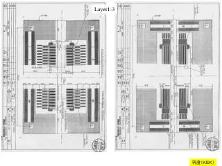
Layer1-3. A’. A. B. B’. 1996 年度のデザイン 内円にほぼ入る デザインなら可。. 2002年(今回). ストリップの長さ: A, B は 7cm A’,B’ は 3cm ストリップの本数: A,B,A’,B’ ともに、各 200 本 ( 含む floating strips), 読み出しストリップは各 100 本。 すべて、 p-strip を持つ single-sided detector とする。. A 及び A’ の構造. バイアスラインの 内側に 読み出しパッドを 配置すること。( 現在のL5DSSDと同じ )。


Layer1-3
E N D
Presentation Transcript
A’ A B B’ 1996年度のデザイン 内円にほぼ入る デザインなら可。 2002年(今回) ストリップの長さ:A, B は7cm A’,B’は3cm ストリップの本数:A,B,A’,B’ともに、各200本(含むfloating strips), 読み出しストリップは各100本。 すべて、p-stripを持つsingle-sided detectorとする。
A及びA’の構造 バイアスラインの内側に読み出しパッドを配置すること。(現在のL5DSSDと同じ)。 A1 – A5 (A’1-A’5)の各構造は、電気的に区分けされること。 A1(A’1) A2(A’2) A3(A’3) A4(A’4) A5(A’5) 3000 3000 3000 3000 3000 P75x40 70000(30000) for A(A’) 単位 m
B及びB’の構造 バイアスラインの外側に読み出しパッドを配置すること。(現在のL1DSSDと同じ)。 B1 – B5 (B’1-B’5)の各構造は、電気的に区分けされること。 B1(B’1) B2(B’2) B3(B’3) B4(B’4) B5(B’5) 3000 3000 3000 3000 3000 P75x40 70000(30000) for B(B’) 単位 m
50 50 50 50 A1, A’1, B1, B’1のアルミ電極 L1DSSDと同じ構造 アルミ電極 p+ strip 56 3 単位 m 75
50 50 50 50 A2, A’2, B2, B’2のアルミ電極 L1DSSDから、floating strip上のアルミ電極を除去した構造 アルミ電極 p+ strip 56 75 3 単位 m
50 50 50 50 20000 20000 20000 A3, B3 のアルミ電極 A2, B2,のアルミ電極に、張り出し部(Overhang)を導入し、interstrip capacitance を大きくした構造。Overhang部の電極の幅(Wao)は120mとする。 ストリップに沿って見た場合10%の領域でOverhangがある。 (Rao = 0.1). アルミ電極 Overhang 56 Wao = 120 p+ strip 10 25 20000 20000 20000 70000 20000 1750 20000 20000 32 75 3 単位 m
50 50 50 50 20000 20000 20000 A4, B4 のアルミ電極 A3, B3と同様、張り出し部(Overhang)を導入するが、Overhangの長さ(ストリップに直行する方向)を長くした構造(Wao=160m)。 ストリップに沿って見た場合10%の領域でOverhangがある。 (Rao=0.10).トータルのinterstrip capacitanceはA3, B3より 大きい。 アルミ電極 Overhang 56 160 p+ strip 30 25 20000 20000 20000 70000 20000 1750 20000 20000 52 75 3 単位 m
50 50 50 50 A5, B5 のアルミ電極 A3, B3と同様、張り出し部(Overhang)を導入するが、floating strip上のアルミ電極を 用いる。トータルのinterstrip capacitanceはA3, B3に同じ。 アルミ電極 Overhang 56 120 p+ strip 10 25 10 20000 20000 20000 10 20000 20000 1750 70000 20000 20000 20000 20000 32 10 75 3 3 単位 m
Co Co large large large Ci Ci extra C Cb Cb Cb Capacitive Network Efficiency vs. Wao Rao = 0.1 is used Husson’s Model is used. Ctot A Co A with extra C B w/o extra C Cb B A B