Download
1 / 15
150 likes | 172 Views
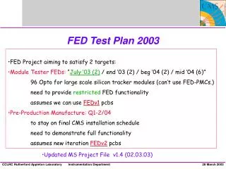
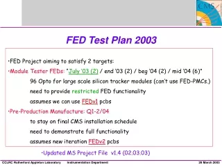
FED Test Plan 2003. FED Project aiming to satisfy 2 targets: Module Tester FEDs: “ July ‘03 (2) / end ‘03 (2) / beg ‘04 (2) / mid ‘04 (6)” 96 Opto for large scale silicon tracker modules (can’t use FED-PMCs.) need to provide restricted FED functionality assumes we can use FEDv1 pcbs

E N D
FED Test Plan 2003 • FED Project aiming to satisfy 2 targets: • Module Tester FEDs: “July ‘03 (2) / end ‘03 (2) / beg ‘04 (2) / mid ‘04 (6)” • 96 Opto for large scale silicon tracker modules (can’t use FED-PMCs.) • need to provide restricted FED functionality • assumes we can use FEDv1 pcbs • Pre-Production Manufacture: Q1-2/04 • to stay on final CMS installation schedule • need to demonstrate full functionality • assumes new iteration FEDv2pcbs • Updated MS Project File v1.4 (02.03.03)
ST, IC, JC -------------------------------------> EF ------------> CMS Tracker FED Schedule Production & Installation Design Test Pre-Pro FEDv1 (20) FEDv2 (20) FEDv3 (500) • FED x 450 installation at CERN expected to start Q3 2005
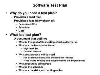
FEDModule Testers Requirements July ‘03 • Paraphrase... • “To Readout Virgin Raw Data formatted as DAQ events via VME in response to TTC trigger and clock.” • With 96 OptoRx chans. Trigger & Readout rates are not critical. • Functionality • Does require: • Scope Mode and Software Triggers for set up. • Controls from VME for run mode, clock source, clock skew, OptoRx offsets, Counters for triggers & errors • VME accessible Event buffer occupancy & lengths for readout. • System ACE loading, Resets on TTC Chan A, Hardware throttle output. • FED delivered as a Package including Software to drive the Firmware. • Does not require: • S-LINK readout, Clustering mode, Spy Channel, TTC chan B, TCS (but maybe simple throttle), DAC control, pedestal/threshold data, System ACE interface, VME64x config EPROM…, VME Interrupts, Temp chip control…
FEDPre-Production FEDv2 • Does require : • S-LINK readout, Clustering mode, Spy Channel, TTC chan B, TCS (but maybe simple throttle), DAC control, pedestal/threshold data, System ACE control and in situ-programming, VME64x config EPROM…, VME Interrupts, Temp chip control… • All operating at target Trigger Rate of 100 kHz! • … FEDv1 is designed for this. • Assumption: have to demonstrate full functionality before pre-production FEDv2.
FEDTesting so far End of Q1. Already achieved in Testing: Boards passed JTAG. Basic FE Analogue tests (with Cross-Point card.) Analogue data capture with Chip Scope. FPGA configuration from System ACE CFlash card. Tested DDR from Delay to FE FPGA. Tested basic external VME interface (with Block Transfer.) First Opto signal tests. Further tests at Imperial. Experience is positive so far. Testing is progressing well. Some “patches” needed on the board. Mainly in Power block. But so far no “show stoppers” for Module Testers with FEDv1 design. Effort now concentrates on implementing and testing remaining Firmware. Concentrating on Module Tester functions.
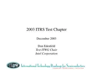
12 12 12 12 12 12 12 12 FED Overview 96 Tracker Opto Fibres CERN Opto- Rx Modularity 9U VME64x Form Factor Modularity matches Opto Links 8 x Front-End “modules” OptoRx/Digitisation/Cluster Finding Back-Endmodule / Event Builder VME module / Configuration Power module Other Interfaces: TTC : Clk / L1 / BX DAQ : Fast Readout Link TCS : Busy & Throttle VME : Control & Monitoring JTAG : Test & Configuration 9U VME64x Analogue/Digital JTAG FPGA Configuration Compact Flash FE-FPGA Cluster Finder VME Interface VME-FPGA BE-FPGA Event Builder TCS TTC TTCrx DAQ Interface Buffers Power DC-DC Temp Monitor Front-End Modules x 8 Double-sided board Xilinx Virtex-II FPGA TCS : Trigger Control System
FEDFirmware Status: Ready to start installing Final Designs on FED together with test firmware. Delay FPGA: Final version synthesised and under test. FE FPGA: Final version synthesised and “ready” for test. BE FPGA: Data path up to QDR filling synthesised and ready for test. TTC chan A interface implemented. Read path to VME in progress incl DAQ formatting. VME FPGA: External VME cycles tested. Serial comms to BE close to test. To do... parallel link to BE incl. readout interface. Steps towards providing Module Test functionality...
FEDv1 Firmware Subtasks System ACE EPROM VME FPGA Ed EPROM System ACE VME Bus Temp VME Opto Rx DAC ADC Opto Rx DAC I2C ADC Clocks Serial Comms VME LINK Clocks Serial Comms Regs Clocks Serial Comms Regs Input Data Data Header Mode Header Mode Cluster Mode BE FPGA Saeed Input FIFOs DELAY FPGA x 3 x 8 Scope Mode Output Scope Mode Serial Comms Regs VME Link Ed Control S-LINK S-LINK FE FPGA x 8 Bill / Ivan Headers Throttle Trigger Simulated Input QDR Write QDR Read TTC chanA Tested on FED TTCrx Control Ed, John, ANON FEDv2 Chan B QDRs Data Saeed, Ivan, ANON
FEDFirmware Tasks in Q2/03 • Load Final Delay FPGA design. Test DDR to FE FPGA using ChipScope. • Test Serial Comms and Readback: From VME -> BE -> FE -> Delay FPGA • Tests OptoRx controls, ADC clock skew. Requires software. • VME end nearly ready. BE take receiver block from FE design. Provide simple register map and test with software. (Later extend to other controls eg to test clock skewing.) NB Uses Final design of FE, Delay and VME. Test design in BE. • Load Final FE FPGA design. Test DDR inputs, Scope Mode and FIFO outputs. • Meanwhile Test Final BE design writing to QDR. Inputs from FE FPGA in Scope Mode. • Extend BE to test QDR readout to VME. • Add Event/Header formatting for readout. • Test parallel link from BE to VME and readout protocol. Readout via CPU.
FEDFirmware Tasks in Q2/03 • Test Readout interfacetoCPU, poll on VME buffer with register for event length. Software needed. • Use TTC to provide ext clock and trigger. Mostly implemented. But need TTC VME cards to do this test. Need clock and trigger select logic. • Test Final FEVirgin Raw data mode (header finding.) Need APV frame generator (OptoTest Card?) Add synch clock and trigger inputs (TTC or backplane?). Need clock and trigger select logic. • Add Control registers & Counters for nr triggers, (resets), errors…. In BE read by VME. • Revised Test Plan v1.3 in progress.
FEDQ2/03 schedule comments • When 2nd Opto Test Card ready put 2 OptoRx on ser 002. • Request for Matt at Ral to get Opto tests going. • Assume deliver 2 FEDs by end of July. Do they really need 2? • Put 8 OptoRx on both 001 (and 002) during CMS week. • Assemble remaining 4 PCBs at same time. • Availability of SBS interface? • Availability of LHC crates? • Other work outside RAL, in addition to software... • Can TTCvi tests be done at Imperial? And Trigger throttle? • Looking ahead to FEDv2 Q3-4… • S-LINK “direct” tests with FED Kit (could start early.) • System ACE interface firmware/software. • TTC chan B firmware for APVE.
FEDTest Software Software: Up to now only peek & poke program to VME from Linux. Good enough for really basic firmware tests. But Module Testers need to integrate FED software into the XDAQ system. And we would like some easy (GUI driven) to use compatible test software. Need FED Application Programming Interface. A list of software functions FED responds to. Need register map/list. Basic low level code needed to... 1. Serial string commands to load and read back FE/DelayFPGA registers as described by Bill. Still to add similar commands for BE FPGA registers. 2. Readout routine. Opportunity for outside involvement. Nb Needs close working with Firmware developers. Online Software to be discussed with Jonathan et al.
FEDv1 FEDv1 Memory Map 8 x 8 KB blocks Offset Reserved Given FEDv1 64 KB A32 address range E000 Reserved Using a “poor man’s” Geographic Addressing scheme... Base Address: Bits 21-16 = Slot number E.g. $0011’0000 - 0011’ffff for slot 17 C000 Reserved A000 Restrictions: A32 Slave D32 access only. Single Access and Block Transfers (no BT to C&S regs) VME Buffer 8000 Serial Read Back 6000 Serial Commands 4000 Test Memory Block RAMs 2000 Control & Status 0000 Read Only ID
FEDv1 Event Readout Protocol • Readout (via VME) Formatted Events identical to those sent to S-LINK • Load Parameters e.g. Peds, Clock skews • Set run mode • Select clock and trigger source • Start Run and enable Triggers/Frames • Poll on VME buffer status • Get length of event • Readout the event (in buffer sized chunks) • Reset VME buffer status • Repeat until Run stop • Periodically look at local status registers and counters to check everything is OK DAQ Header Tracker Header Formatted FED Data DAQ Trailer Event Formats: Virgin Raw Data. Raw APV frames. *Scope Mode or Software Trigger Both are fixed event sizes within a Run. (*Empty Tracker Header.)
FEDTest Equipment • Cross-Point cards available for electrical inputs. Most useful in Scope modes. • Second Opto Test card for RAL (after Easter). Most convenient for APV patterns. Needed for Raw Data (header finding) readout tests with FE FPGA. • Have TTC VME cards in hand at IC and RAL. • FED Kit in hand at IC and RAL. • New PC/VME Interface (SBS optical link card) by Easter? • Standard LHC VME64x Crate by ? • FED Kit in hand at IC and RAL.