Download
1 / 36
360 likes | 382 Views
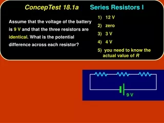
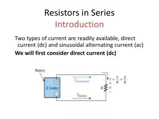
RESISTORS IN SERIES - In a series circuit, the current is the same at all points along the wire. I T = I 1 = I 2 = I 3

E N D
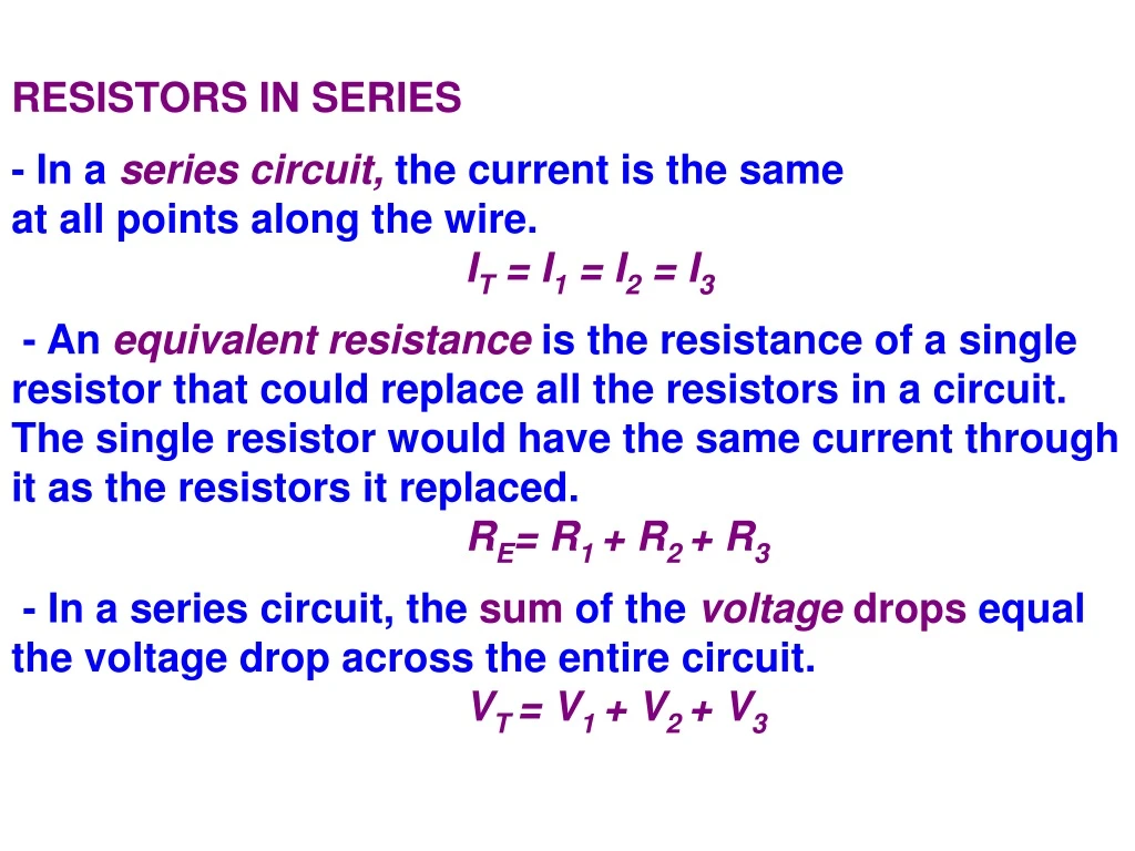
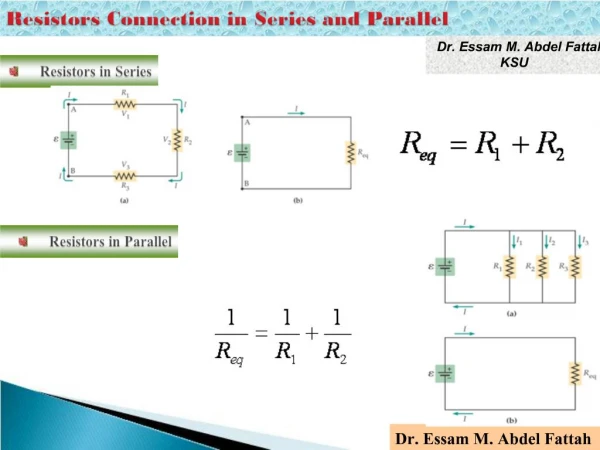
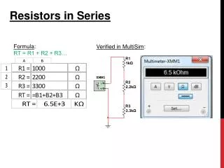
RESISTORS IN SERIES - In a series circuit, the current is the same at all points along the wire. IT = I1 = I2 = I3 - An equivalent resistance is the resistance of a single resistor that could replace all the resistors in a circuit. The single resistor would have the same current through it as the resistors it replaced. RE= R1 + R2 + R3 - In a series circuit, the sum of the voltage drops equal the voltage drop across the entire circuit. VT = V1 + V2 + V3
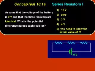
19.1 Two resistances of 2 Ω and 4 Ω respectively are connected in series. If the source of emf maintains a constant potential difference of 12 V, a. What is the current delivered to the external circuit? Re = R1 + R2 = 2 + 4 = 6 Ω = 2 A b. What is the potential drop across each resistor? V1 = I R1 = 2(2) = 4 V V2 = I R2 = 2(4) = 8 V
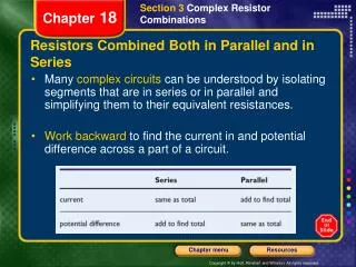
PARALLEL CIRCUITS - In a parallel circuit, each resistor provides a new path for electrons to flow. The total current is the sum of the currents through each resistor. IT = I1 + I2 + I3 - The equivalent resistance of a parallel circuit decreases as each new resistor is added. - The voltage drop across each branch is equal to the voltage of the source. VT = V1 = V2 = V3
19.2 The total applied voltage to the circuit in the figure is 12 V and the resistances R1, R2 and R3are 4, 3 and 6 Ω respectively. a. Determine the equivalent resistance of the circuit. R2 and R3 are in parallel (RP) Rp= 2 Ω RP and R1 are in series Req= 4 + 2 = 6 Ω
b. What is the current through each resistor? I1 = 2 A (series) V1 = IR1 = 2(4) = 8 V = 2 A The voltage through the parallel combination is therefore: 12-8 = 4 V each = 0.67 A = 1.33 A
19.3 Find the equivalent resistance of the circuit shown. 19 and 5 are in series: 19 + 5 = 24 Ω this combination is in parallel with 8: RP = 6 Ω this combination is in series with 15: 15 + 6 = 21 Ω this in turn is in parallel with 9: RP= 6.3 Ω finally the equivalent resistance: Req= 6.3 + 2 + 0.2= 8.5 Ω
19.4 A potential difference of 20 V is applied to the circuit in the figure below. Find the current through the entire circuit and the current through each resistor. R1and R2are in parallel: RP= 5 Ω this combination is in series with R3: 5 + 3 = 8 Ω this combination is now in parallel with R4: RP= 4.8 Ω = Req
= 4.17 A IT = I3 + I4 = 1.67 A I3 = IT - I4 = 4.17 - 1.67 = 2.5 A
The voltage for the parallel combination is: V' = V - I3R3 = 20 - (2.5)(3) = 12.5 V = 1.25 A I2= 2.5 - 1.25 = 1.25 A
EMF AND TERMINAL POTENTIAL DIFFERENCE Every source of emf(ξ ) has an inherent resistance called internal resistance represented by the symbol r. This resistance is a small resistance in serieswith the source of emf. The actual terminal voltage VT across a source of emf with an internal resistance is given by: VT = ξ - I r Units: Volts (V)
19.5 A load resistance of 8 Ω is connected to a battery whose internal resistance is 0.2 Ω a. If the emf of the battery is 12 V, what current is delivered to the load? ξ = 12 V RL = 8 Ω r = 0.2 Ω = 1.46 A b. What is the terminal voltage of the battery? VT = ξ - I r = 12 - 1.46(0.2) = 11.7 V
19.6 a. Determine the total current delivered by the source of emf to the circuit in the figure. Voltage = 24 V. The resistances are 6, 3, 1 and 2 Ω respectively. R1and R2are in parallel: RP= 2 Ω this combination is in series with R3: 2 + 1 = 3 Ω this combination is now in parallel with R4: RP = 1.2 Ω
finally the internal resistance is in series giving the equivalent resistance: Req= 1.2 + 0.4 = 1.6 Ω = 15 A
b. What is the current through each resistor? VT = ξ - I r = 24 - 1.5(0.4) = 18 V V4 = VT = 18 V I3 = IT - I4 = 15 - 9 = 6 A = 9 A
V3 = I3R3 = 6(1) = 6 V V1 = V2 = 18 - 6 = 12 V each = 2 A = 4 A
KIRCHHOFF’S LAWS An electrical network is a complex circuit consisting of current loops. Kirchhoff developed a method to solve this problems using two laws. Law 1. The sum of the currents entering a junction is equal to the sum of the currents leaving that junction. Law 2. The sum of the emfs around any closed current loop is equal to the sum of all the IR drops around that loop. (Ohm’s Law: V = IR)
A junctionrefers to any point in the circuit where two or three wires come together.
APPLYING KIRCHHOFF’S LAW We will use the following circuit to explain the procedure suggested by Kirchhoff:
1. Assume a current direction for each loop in the network: I1 counterclockwise
I2 counterclockwise I3 counterclockwise
2. Apply Kirchhoff's first law to write a current equation for all but one of the junction points. The equation for junction m is: Σ Ientering = Σ Ileaving I1 + I2 = I3
3. Indicate by a small arrow the direction in which each emfacting alone would cause a positive charge to move. ξ 1 and ξ 2 are directed to the left and ξ 3 is directed to the right.
4. Apply Kirchhoff's second law for one loop at a time. There will be one equation for each loop. One must begin at a specific point on a loop and trace around the loop in a consistent direction. The tracing direction is always positive. The following sign conventions apply: a. When adding emfs, the value assigned to the emf is positive if its output is with the tracing direction. The emf is negative if its output is against the tracing direction. b. An IR drop is positive when the assumed current is with the tracing direction and negative when the assumed current is against the tracing direction.
Loop 1 Starting at point mand tracing clockwise, we have: - ξ 1 + ξ 2 = - I1R1 + I2R2
Loop 2 Starting at point mand tracing counterclockwise, we have: ξ 3 + ξ 2 = I3R3 + I2R2
Loop 3 Starting at m and tracing counterclockwise we have: ξ 3 + ξ 1 = I3R3 + I1R1
We now have three independent equations involving only three unknowns, and the third loop equation can be used to check the results. In order to solve the equations you may use your calculator with MATRIX mode.
Consider the circuit in the drawing. Determine 19.7 Consider the circuit in the drawing. Determine (a) the magnitude of the current in the circuit and (b) the magnitude of the voltage between the points labeled A and B. + +
The current I can be found by using Kirchhoff’s loop rule. Once the current is known, the voltage between points A and B can be determined a. We assume that the current is directed clockwise around the circuit. Starting at the upper left corner and going clockwise we ger (5.0Ω)I + (27 Ω) + 10.0 V + (12 Ω) I + 8.0 Ω I = 30.0V Solving for I we get I = 0.38 Amps
SECOND LAW: Σ V = Σ IR right loop: - 3 V = I3 (2 Ω) + I3 (4 Ω) + I2 (3 Ω) dividing by 1 Ω: - 3 A = 6 I3 + 3 I2 Three equations: I1 - I2 + I3 = 0 I1 + 3 I2 = 8 A I2 + 2 I3 = - 1 A
I1 = 3 A I2 = 1.67 A I3 = - 1.33 A our assumed current direction is incorrect, therefore: I3 = 1.33 A CHECK: Using the outside loop counterclockwise (6 + 2 + 3) V = 1 Ω I1 - 4 Ω I3 - 2 Ω I3 11 A = I1 - 6 I3 substituting our results: 11 A = 3 A - 6 (- 1.33 A) 11 A = 11 A
19.8 Solve for the unknown currents using Kirchhoff's laws. FIRST LAW: Σ Ientering = Σ Ileaving I2 = I1 + I3 SECOND LAW: Σ V = Σ IR left loop: -20 A = 8 I2 + 10 I1 simplifying: 5 I1 + 4 I2 = -10 right loop: - 4 = 6 I3 + 8 I2 simplifying: 4 I2 + 3 I3 = - 2
Three equations: I1 - I2 + I3 = 0 5 I1 + 4 I2 = -10 4 I2 + 3 I3 = - 2 I1 = - 1.32 AI2 = - 0.85 AI3 = 0.47 A our assumed current direction for I1 and I2 is incorrect. CHECK: Using the outside loop clockwise 20 - 4 = - 10 I1 + 6 I3 substituting our results: 16 = - 10(-1.32) + 6 (0.47) 16 A = 16.02 A


![[Series Circuit]](https://cdn1.slideserve.com/2747272/series-circuit-dt.jpg)