
Basic Vibration Analysis
E N D
Presentation Transcript
Basic Vibration Analysis ACES Systems/TEC Aviation Division sales@acessystems.com support@acessystems.com 06/06/2011 #1
Overview • What is Vibration? • Terminology • Equipment • How Vibration Is Analyzed • Types of Vibration Surveys • Interpreting a Vibration Survey • Basic Balancing • Predictive Maintenance 06/06/2011 #2
What is Vibration? Vibration is the physical movement or oscillation of a mechanical part about a reference position. 06/06/2011 #3
What Is Vibration?Why do we care? • Vibration is: • Wasted energy • A major cause of premature component failure • Cause of aircraft noise which contributes to crew and passenger discomfort 06/06/2011 #4
Terminology Prior to any discussion of vibration, it is important to first understand the common terms used for vibration analysis and their applications. 06/06/2011 #5
The rate of mechanical oscillation in a period of time. Frequency can be expressed in one of the following units: RPM - Revolutions per Minute CPM - Cycles per Minute CPS - Cycles per Second Hz - Hertz, 1 Hz - 1 Cycle per Second (to convert from Hz to RPM or CPM, apply the following formula: Hz * 60 = RPM. TerminologyFrequencies 06/06/2011 #6
TerminologyAmplitude • Amplitude is an indicator of the severity of a vibration. Amplitude can be expressed as one of the following engineering units: • Velocity • Acceleration • Displacement 06/06/2011 #7
TerminologyVelocity • Velocity is the rate of change in position • Typical velocity units are: IPS (Inches Per Second), mm/sec (millimeters per second) • Velocity is the most accurate measure of vibration because it is not frequency related. 0.5 IPS @ 1000 rpm is the same as 0.5 IPS @ 10000 rpm. 06/06/2011 #8
TerminologyAcceleration • Acceleration is the rate of change of velocity and is the measurement of the force being produced. • Acceleration is expressed in gravitational forces or “G’s”, (1G = 32.17 ft/sec/sec) • Acceleration is frequency related, in that 1 g @ 1000 rpm is not the same as 1 g @ 10000 rpm. 06/06/2011 #9
TerminologyAcceleration • 1g @ 1000 RPM = 1g @ 16.7 Hz • IPS = (61.44 x 1.0) / 16.7 • IPS = 3.7 • 1g @ 10000 RPM = 1g @ 166.7 Hz • IPS = (61.44 x 1.0) / 166.7 • IPS = 0.37 06/06/2011 #10
TerminologyDisplacement • Displacement is a measure of the actual distance an object is moving from a reference point. • Displacement is expressed in “mils” 1 mil = .001 inch • Displacement is also frequency related, in that 10 mils @ 1000 rpm is not the same as 10 mils @ 10000 rpm. 06/06/2011 #11
TerminologyDisplacement • 10 mils @ 1000 RPM = 0.010 @ 16.7 Hz • IPS = (3.14 x 16.7) x 0.010 • IPS = 0.52 • 10 mils @ 10000 RPM = 0.010 @ 166.7 • IPS = (3.14 x 166.7) x 0.010 • IPS = 5.23 06/06/2011 #12
TerminologyUnit Modifiers Unit Modifiers: Since vibration is transmitted as an AC signal, there are four Unit Modifiers that may be used to condition the signal. These modifiers have a direct impact on the measurement value. If the wrong modifier is used, the measurement could be either too high, or too low, thus causing possible maintenance action to be, or not to be, accomplished erroneously. 06/06/2011 #13
Unit Modifiers: Peak to Peak - the distance from the top of the positive peak to bottom of the negative peak. Peak- the measurement from the zero line to the top of the positive peak. Average(AVG) - .637 of peak. Root Mean Square(RMS) - .707 of peak. 06/06/2011 #14
TerminologyUnit Modifiers If I’m testing an engine whose limit is 1.0 IPS Pk-Pk and my analyzer shows a measurement of 0.6 IPS Pk, does the engine pass or fail? Fail. Why? Fail. 0.6 IPS Pk * 2 = 1.2 IPS Pk-Pk 06/06/2011 #15
Types of Vibration • Vibration can be classified into one or more of the following categories: • Periodic • Random • Resonant • Harmonic 06/06/2011 #16
Terminology - Types of VibrationPeriodic • Repeats itself once every time period • Result of a mass imbalance in a component or disc. • As the component rotates, it produces a “bump” every rotation which is referred to a the once-per-revolution or “1P” vibration. • This vibration is usually correctable by balancing. 06/06/2011 #17
Terminology - Types of VibrationRandom • Do not repeat themselves • Not related to a fundamental frequency. • An example - the shock that is felt as a result of driving down the road and hitting a pothole 06/06/2011 #18
Terminology - Types of VibrationResonant • The natural frequency at which an airframe or mechanical system is inclined to vibrate. All things have one or more resonant frequencies. • Resonant vibrations are the result of a response in a mechanical system to a periodic driving force. 06/06/2011 #19
Terminology - Types of VibrationHarmonic • Exact multiples of a fundamental frequency • Classified in terms as 1st, 2nd, 3rd….. 06/06/2011 #20
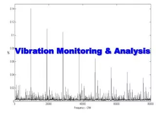
TerminologyBandwidth • Upper and lower frequency limits of the survey being acquired - either hardware set (with the use of an external band pass filter) or software controlled by the analyzer. • Setting the frequency bandwidth is a way of eliminating vibration data or noise that is of no interest for your particular application. • In the survey above, the frequency bandwidth is 0 CPM to 3000 CPM 06/06/2011 #21
TerminologyResolution • The resolution of a spectrum is the number of lines or points used to plot the spectrum. • The higher the number of lines, the more data acquired. 06/06/2011 #22
Equipment • Sensor • A transducer that converts mechanical motion into electronic signals. • Three categories: • Displacement • Velocity • Accelerometer 06/06/2011 #23
OUTPUT CONNECTOR AND AMPLIFIER PRELOAD SCREW SEISMIC MASS PIEZOELECTRIC ELEMENT IN COMPRESSION PEDESTAL BASE EquipmentSensor Construction 06/06/2011 #24
Sensor TypeDisplacement • Measures the distance an object is moving from a reference position. This distance is typically reported in mils. • Most accurate in frequencies below 10 Hz, or 600 RPM 06/06/2011 #25
Sensor TypeVelocity • Measures the rate of change of position an object is moving, and is commonly reported in Inches Per Second (IPS) • Best suited to measure vibrations between ~ 10 Hz and 1000 Hz, or 600 to 60000 RPM. 06/06/2011 #26
Sensor TypeAccelerometer • Measures the rate of change of velocity per time period. Acceleration is reported in Gs • Most effective frequency range for an accelerometer is above 1000 Hz, or 60000 RPM. 06/06/2011 #27
Sensor Selection • The first consideration is the manufacturer’s recommendation. If none exist, then: • Frequency Range • Environmental conditions 06/06/2011 #28
Sensor Installation • Varies depending upon the application. • Most manufacturers provide the specific location for mounting and this should be strictly adhered to. If these recommendations are not followed, the resulting measurements may be invalid. • Generally, mount in a location that provides the closest proximity to the component of interest. 06/06/2011 #29
How Vibration Is Analyzed • Time Domain - Vibration vs. Time. • A vibration signal is presented as a sin wave form with all frequencies and amplitudes combining to give one overall signal. 06/06/2011 #30
What a Vibration Sensor Sees Signals from four helicopter component vibrations: Main Rotor 1x, Main Rotor 2x, Tail Rotor, and Tail Rotor Drive combined by the vibration sensor to produce one signal. This would be difficult at best to use as a means of determining vibration faults in mechanical structure. 06/06/2011 #31
Separated, the four signals are distinguishable. To separate the signals, a conversion is required. 06/06/2011 #32
How Vibration Is Analyzed • Frequency Domain • By applying the FFT (Fast Fourier Transform) algorithm to a Time Domain signal, it is converted to the Frequency Domain. • In the Frequency Domain, each individual amplitude and frequency point are displayed. 06/06/2011 #33
The Frequency domain spectra shown here has separated all four of the components listed earlier, Main Rotor 1x, 2x, Tail Rotor, and Tail Rotor Drive, into their own individual points showing both the frequency (RPM) and Amplitude (IPS). 06/06/2011 #34
Types of Vibration Surveys • Overall Vibration • Steady State • Transient • Synchronous • Peak Hold All have a very specific application. 06/06/2011 #35
Types of Vibration SurveysOverall Vibration • Outputs the sum of all vibration measured within a specified frequency range. • Used as an initial “alarm” type survey, whereby if the overall indication is above a specified value, a more detailed survey is performed to identify the possible cause. 06/06/2011 #36
Types of Vibration SurveysSteady State • Used to measure vibration at a constant engine/component operational frequency. • Used to determine thespeed / frequency at which balancing should be performed. It can also be used to identify critical operationalconditions. 06/06/2011 #37
Types of Vibration SurveysTransient • Data collected during a controlled change in the aircraft / component operational frequency. • Often used in trending vibration over time by comparing surveys taken at specified intervals. 06/06/2011 #38
Types of Vibration SurveysPeak Hold • The maximum amplitude value measured is captured and held. 06/06/2011 #39
Types of Vibration SurveysSynchronous • Utilizes a tachometer signal and a filter to track vibration of a specific rotor or shaft. The filter eliminates all vibrations above and below the tachometer signal input plus or minus the filter value. • Used to determine the amplitude and phase (clock) angle of an imbalance condition. 06/06/2011 #40
Interpreting a Vibration Survey • Define the frequency range • Identify component frequency. • Frequency charts • Multiple components within a system such as a gearbox will have the ratio listed versus some operational speed of the assembly, typically 100 %. 06/06/2011 #41
Interpreting a Vibration SurveyUsing a Normal Cursor • Modern digital analysis equipment provides for identification of frequencies within a spectral plot with the use of a cursor. • When the cursor is placed over a peak in the plot, the specific frequency and amplitude values for that point are displayed. 15300 RPM > 0.324 Amplitude > 06/06/2011 #42
Interpreting a Vibration SurveyUsing a Harmonic Cursor Harmonic Cursor Using the same example as before,the harmonic multiples of theprimary peak identified can also beidentified by using the harmonicoption (if available). When theharmonic function is pressed, the analyzer will position oneadditional cursor at each of the multiples throughoutthe range. 06/06/2011 #43
Basic Balancing • Mass Imbalance • Aerodynamic Imbalance 06/06/2011 #44
Fundamentals of BalancingData Collection and Processing • The vibration sensor is installed on the engine as near the front bearing as possible. • The Phototach is mounted on the cowling, behind the propeller. • The reflective tape is applied to the back side of the target propeller blade in line with the Phototach beam. • The mass is located by the relative occurrence of tach trigger and mass passage at the radial sensor location. 06/06/2011 #45
Fundamentals of BalancingData Collection and Processing • As the heavy spot on the propeller passes the location of the vibration sensor, the sensor generates and sends an electrical pulse to the analyzer. • The Reflective tape triggers a response as it passes the Phototach, which then sends an electrical signal to the analyzer. 06/06/2011 #46
Fundamentals of BalancingData Collection and Processing • In this illustration, the vibration sensor and Phototach beam are co-located at the 12:00 or 0 degree position. Rotation is clock-wise from the viewers position. This is our starting point, elapsed time = 0 06/06/2011 #47
Fundamentals of BalancingData Collection and Processing • The speed is 1 RPM. Fifteen seconds (90 degrees) of travel has occurred. In this sequence, the reflective tape has just entered the Phototach beam to trigger the tach event. Elapsed time = 15 seconds. 06/06/2011 #48
Fundamentals of BalancingData Collection and Processing • In this sequence, the mass (heavy spot) is passing the accelerometer position, 15 seconds (90 degrees) after the tape passed the Phototach beam. Elapsed time = 15 seconds (90 degrees of travel). 06/06/2011 #49
Fundamentals of BalancingData Collection and Processing • The tape and mass have both passed the 0 degree location. The unit now waits for the exact sequence to repeat for averaging. • Solution would be to add weight at 270 degrees. 06/06/2011 #50