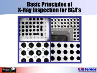
Basic elements of the x-ray assembly source
740 likes | 760 Views
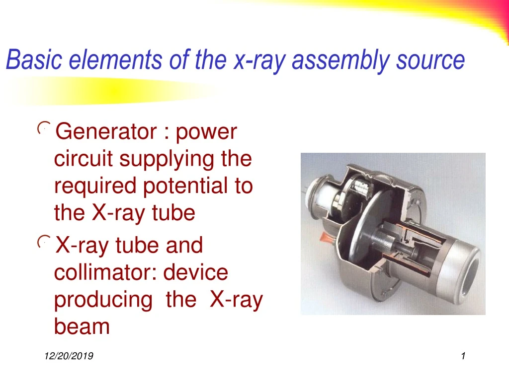
Basic elements of the x-ray assembly source. Generator : power circuit supplying the required potential to the X-ray tube X-ray tube and collimator: device producing the X-ray beam. X-ray generator (II).

Basic elements of the x-ray assembly source
E N D
Presentation Transcript
Basic elements of the x-ray assembly source • Generator : power circuit supplying the required potential to the X-ray tube • X-ray tube and collimator: device producing the X-ray beam
X-ray generator (II) • Generator characteristics have a strong influence on the contrast and sharpness of the radiographic image • The motion unsharpness can be greatly reduced by a generator allowing an exposure time as short as achievable • Since the dose at the image plane can be expressed as : D = k0 . kVpn . I . T • kVp : peak voltage (kV) • I : mean current (mA) • T : exposure time (ms) • n : ranging fromabout 3at 150 kVto 5at 50 kV
X-ray generator (III) • Peak voltage value has an influence on thebeam hardness • It has to be related to medical question • What is the anatomical structure to investigate ? • What is the contrast level needed ? • The ripple “r” of a generator has to be as low as possible r = [(kV - kVmin)/kV] x 100%
Thin Target X-ray Formation Interestingly, this process creates a relatively uniform spectrum. Maximum energy is created when an electron gives all of its energy, 0 , to one photon. Or, the electron can produce n photons, each with energy 0/n. Or it can produce a number of events in between. Power output is proportional to 02 Intensity = nh 0 Photon energy spectrum
Thick Target X-ray Formation We can model target as a series of thin targets. Electrons successively loses energy as they moves deeper into the target. Gun X-rays Relative Intensity 0 Relative Intensity Each layer produces a flat energy spectrum with decreasing peak energy level.
Energy (eV) K1 100 80 60 40 20 - 20 - 70 - 590 - 2800 - 11000 - 69510 K2 6 5 4 3 2 0 P K1 O N L L K2 M L L 0 10 20 30 40 50 60 70 80 (keV) K Spectral distribution of characteristic X-rays (II)
Thick Target X-ray Formation Andrew Webb, Introduction to Biomedical Imaging, 2003, Wiley-Interscience. ( Lower energy photons are absorbed with aluminum to block radiation that will be absorbed by surface of body and won’t contribute to image. The photoelectric effect will create significant spikes of energy when accelerated electrons collide with tightly bound electrons, usually in the K shell.
Factors influencing the x-ray spectrum X-ray spectrum at 30 kV for an X-ray tube with a Mo target and a 0.03 mm Mo filter • tube potential • kVp value • wave shape of tube potential • anode track material • W, Mo, Rh etc. • X-ray beam filtration • inherent + additional 15 10 5 Number of photons (arbitrary normalisation) 10 15 20 25 30 Energy (keV)
Stopping power • Loss of energy along track through collisions • The linear stopping power of the medium S = E / x [MeV.cm-1] • E: energy loss • x: element of track • for distant collisions : the lower the electron energy, the higher the amount transferred • most Bremsstrahlung photons are of low energy • collisions (hence ionization) are the main source of energy loss • except at high energies or in media of high Z
Linear Energy Transfer • Biological effectiveness of ionizing radiation • Linear Energy Transfer (LET): amount of energy transferred to the medium per unit of track length of the particle • Unit : e.g. [keV.m-1]
Photon interactions with matter Scattered photon Compton effect Secondary photons Fluorescence photon (Characteristic radiation) Annihilation photon Incident photons Non interacting photons Recoil electron Secondary electrons Photoelectron (Photoelectric effect) Electron pair E > 1.02 MeV (simplified representation)
How do we describe attenuation of X-rays by body? Assumptions: Matter is composed of discrete particles (i.e. electrons, nucleus) Distance between particles >> particle size X-ray photons are small particles Interact with body in binomial process Pass through body with probability p Interact with body with probability 1-p (Absorption or scatter) No scatter photons for now (i.e. receive photons at original energy or not at all.
N |∆x|N - ∆N The number of interactions (removals) number of x-ray photons and ∆x ∆N = -µN∆x µ = linear attenuation coefficient (units cm-1)
µ = f(Z, ) Attenuation a function of atomic number Z and energy Solving the differential equation: dN = -µNdx Ninx Nout µ Noutx ∫ dN/N = -µ ∫ dx Nin 0 ln (Nout/Nin) = -µx Nout = Nin e-µx
If material attenuation varies in x, we can write attenuation as µ(x) Nout = Nin e -∫µ(x) dx If Io photons/cm2 (µ (x,y,z)) Id (x,y) = I0 exp [ -∫ µ(x,y,z) dz] Assume: perfectly collimated beam ( for now), perfect detector no loss of resolution Id (x,y) Detector Plane
Actually recall that attenuation is also a function of energy , µ = µ(x,y,z, ) Id (x,y) = ∫ I0 () exp [ -∫ µ (x,y,z,) dz] d Which Integrate over and depth. For a single energy I0() = I0 ( - o) = I0 After analyzing a single energy, we can add the effects of other energies by superposition. If homogeneous material, then µ (x,y,z, 0) = µ0 Id (x,y) = I0 e -µ0∆z
Attenuation of an heterogeneous beam • Various energies No more exponential attenuation • Progressive elimination of photons through the matter • Lower energies preferentially • This effect is used in the design of filters • Beam hardening effect
Half Value Layer (HVL) • HVL: thickness reducing beam intensity by 50% • Definition holds strictly for monoenergetic beams • Heterogeneous beamhardening effect • I/I0 = 1/2 = exp (-µ HVL) HVL = 0.693 / µ • HVL depends on material and photon energy • HVL characterizes beam quality • modification of beam quality through filtration • HVL (filtered beam) HVL (beam before filter)
(HVL) Half Value Layer: • HVL اندازه گيري (معيار) غير مستقيم انرژي فوتون يا كيفيت تشعشع مي باشد. • Homogeneity Coefficient: • از آنجائيكه تشعشع بر مشترالانگ تك انرژي نيست ، مقدار تشعشع كاهش يافته در ضخامت هاي اوليه مثلاً اولين HVL سريعتر از لايه هاي دوم و سوم خواهد بود ولي تشعشع سخت تر مي شود نسبت HVL اول به دوم ضريب يكنواختي نام دارد و پراكندگي انرژي تشعشع را نشان مي دهد
X-ray interaction with matter Coherent Scattering Photoelectric Effect Compton Scattering Pair Production Photodisintegration .
Physical Basis of Attenuation Coefficient Coherent Scattering - Rayleigh • • Coherent scattering varies over diagnostic energy range as: • µ/p 1/2 •• •• • • •
Photoelectric Effect Longest photoelectron range 0.03 cm Fluorescent radiation example: Calcium 4 keV Too low to be of interest. Quickly absorbed Items introduced to the body: Ba, Iodine have K-lines close to region of diagnostic interest.
Photoelectric effect • Incident photon with energyh • Absorption: all photon energy absorbed by a tightly bound orbital electron ejection of electron from the atom • Kinetic energy of ejected electron : Ee = h - EB • Condition : h > EB(electron binding energy) • Recoil of the residual atom • Attenuation (or interaction) coefficient photoelectric absorption coefficient
We can use K-edge to dramatically increase absorption in areas where material is injected, ingested, etc. Photoelectric linear attenuation varies by Z3-4/ 3 ln /r Log () Photon energy K edge
Compton Scatter - Interaction of photons and electrons produce scattered photons of reduced energy. - The probability of interaction decreases as h increases - Compton effect is proportional to the electron density in the medium When will this be a problem? Is reduced energy a problem? Is change in direction a problem? E’ photon E=h = E’+Ee E a Outer Shell electron v Electron (“recoil”)
Satisfy Conservation of Energy and Momentum (m-mo = electron mass : relativistic effects) Conservation of Momentum: 2) 3)
Energy of recoil or Compton electron can be rewritten as h = 6.63 x 10⁻³⁴ Jsec eV = 1.62 x 10⁻¹⁹ J mo = 9.31 x 10⁻³¹ kg ∆ = h/ moc (1 - cos ) = 0.0241 A0 (1 - cos ) ∆ at = π = 0.048 Angstroms Energy of Compton photon
Greatest effect ∆/ occurs at high energy At 50 kev, x-ray wavelength is .2 Angstroms Low energy small change in energy High energy higher change in energy
Mass attenuation coefficient (µ/r) electron mass density Unfortunately, almost all elements have electron mass density ≈ 3 x 10 23 electrons/gram Hydrogen (exception) ≈ 6.0 x 10²³ electrons/gram µ/r for Compton scattering is Z independent Compton Linear Attenuation Coefficient µ p Avg atomic number for Bone ~ 20 Avg atomic number for body 7 or 8
Rayleigh, Compton, Photoelectric are independent sources of attenuation t = I/I0 = e-µl = exp [ -(uR + up + uc)l] µ () ≈ pNg { f() + CR (Z2/ 1.9) + Cp (Z3.8/ 3.2)} Compton Rayleigh Photoelectric Ng electrons/gram ( electron mass density) So rNg is electrons/cm3 Ng = NA (Z/A) ≈ NA /2 (all but H) A = atomic mass f() = 0.597 x 10⁻²⁴ exp [ -0.0028 (-30)] for 50 keV to 200 keV in keV
Attenuation Mechanisms Curve on left shows how photoelectric effects dominates at lower energies and how Compton effect dominates at higher energies. Curve on right shows that mass attenuation coefficient varies little over 100 kev. Ideally, we would image at lower energies to create contrast.
Photoelectric vs. Compton Effect The curve above shows that the Compton effect dominates at higher energy values as a function of atomic number. Ideally, we would like to use lower energies to use the higher contrast available with The photoelectric effect. Higher energies are needed however as the body gets thicker.
X-ray absorption characteristics of iodine, barium and body soft tissue 100 Iodine 10 Barium X-Ray ATTENUATION COEFFICIENT (cm2 g-1) Soft Tissue 1 (keV) 0.1 20 30 40 50 60 70 80 90 100
Contribution of Energy to attenuation of X-rays in bone 10 1.0 Total X-Ray ATTENUATION COEFFICIENT (cm2 g-1) 0.1 Compton + Coherent Photoelectric (keV) 0.01 20 40 60 80 100 120 140
Image formation (Film) • X-ray photons converted to light photons Image before processing • Photoelectric Effect (intensifying screen ) • Film is made to be especially sensitive to the effects of light from an intensifying screen. When these screens, on either side of the film in a cassette, are exposed to x-rays, they emit light which in turn exposes the film. • Latent image Made visible by chemical processing
Silver Halide Crystal 95% of crystal is silver bromide
Silver Halide Crystals • There are two types of silver halide crystals. • Tabular (flat) crystals • The crystals are placed in the emulsion so that the flat surface (top view below) is parallel with the surface of the film. • Globular (rounded) crystals are used in D-speed (Ultraspeed) film; • these crystals are like small pebbles.
Intensifying screen structure • The fluorescent layer (luminophor crystals) should : • be able to absorb the maximum quantity of X-rays • match its fluorescence with the film sensitivity (color of emitted light) • Type of material : • Calcium Tungstate (CaWO4) (till 1972) • Rare earth (since 1970) (LaOBr:Tm) (Gd2O2S:Tb) more sensitive and effective than(CaWO4)
Intensifying screen characteristics • IF (Intensifying Factor): ratio of exposures giving the same film optical density, with and without screen • 50 < IF < 150 (depending on screen material and X-ray beam energy) • QDE (Quantum Detection Efficiency): fraction of photons absorbed by the screen • 40% for CaWO4 < QDE < 75% for rare earth (depending on crystal material, thickness of fluorescent layer and X-ray spectrum) • (Rendering coefficient): ratio of light energy emitted to X-ray energy absorbed (%) • 3% for CaWO4 < < 20% for rare earth • C (Detection Coefficient): ratio of energy captured and used by the film to energy emitted by the crystal (%) • Cis maximum for screens emitting in UV color wave length 90%
Intensifying screen characteristics Sensitivity of a Conventional Film BaSO4:Eu,Sr YTaO4:Nb BaSO4:Pb Relative Sensitivity of Film CaWO4 250 300 350 400 450 500 550 600 UV Blue Green
Intensifying screen characteristics Intensifying factor: ratio of exposures giving the same film optical density, with and without screen 175 150 125 100 75 50 25 0 Gd2O2S LaOBr Intensifying factor CaWO4 kV 50 60 70 80 90 100 110 120
Intensifying Screen Speed • The speed of the screen depends on crystal size and the thickness of the phosphor layer (larger crystals and thicker layer increase speed). Image quality decreases as the screen speed increases. The three speeds are: • Fast (Rapid): requires the least exposure but the images are less sharp • Medium (Par): medium speed, medium sharpness • Detail (Slow): produces the sharpest images but requires the most exposure
Screen film combination • Sensitivity (screen film): The quotient K0/Ka, where K0 = 1 mGy and Ka is the air kerma free-in-air for the net density D = 1.0, measured in the film plane • Screen film system: A particular intensifying screen used with a particular type of film • Sensitivity class: Defined range of sensitivity values of a screen film system • Singleemulsion film: One coated film used with one intensifying screen • Double emulsion film: A double coated film used with a couple of intensifying screens • Screen film contact Quantum mottle
Screen film combination performance • Spatial Resolution: capability of a screen film combination to display a limited number of line pairs per mm. It can be assessed by the Hüttner resolution pattern. • Modulation Transfer Function (MTF): description of how sinusoidal fluctuations in X-ray transmission through the screen film combination are reproduced in the image • Noise spectrum: component of noise due to intensifying system (screen film) • Quantum noise, Screen noise, Granularity
Screen film combination performance • Identification of screen by type and format • type mismatch (use of different types of screens) FOR THE SAME FORMAT is not ADVISABLE • Screen film contact • loss of spatial resolution • blurred image • Cleanliness • Inter cassette sensitivity