Download
1 / 49
700 likes | 2.6k Views
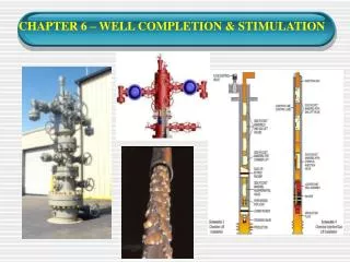
CHAPTER 6 – WELL COMPLETION & STIMULATION . CONTENTS. What is Well Completion. Setting Production Casing. Installing the Tubing. Installing the Christmas Tree Types of Well Completion Factors Influencing Well Completion Selection Type of Flow Completion and Workover Fluids Perforating

E N D
CONTENTS What is Well Completion. Setting Production Casing. Installing the Tubing. Installing the Christmas Tree Types of Well Completion Factors Influencing Well Completion Selection Type of Flow Completion and Workover Fluids Perforating Well Stimulation
What is Well Completion? • After careful interpretation and consideration on well test data (coring, logging etc), a decision is made whether to set production casing and complete the well or to plug and abandon it. • Decision to abandon is made when the well is not capable to produce oil or gas in commercial quantities. • However, sometimes wells that were plugged and abandoned at one time in the past may be reopened and produced if the price of oil or gas has become more favorable. • “Completing a well” means installing equipment in the well to allow a safe and controlled flow of petroleum from the well.
A series of activities to prepare an oil well or a gas well, so that the well can be flowed in a controlled manner. All wells have to be completed. • In addition to the casing that lines the wellbore (recall Chapter 4), tubing and a system of flow valves must be installed. • Cannot operate alone - must joint effort with other sub-disciplines such as production engineering and reservoir engineering.
1. Semi Submersible Location of Various Nodes in Production System
Setting Production Casing • Production casing is the final casing in a well. • The hole is drilled beyond the producing interval. • Production casing is set and cemented through the pay zone. • The casing and cement actually seal off the producing zone Installing production casing
Installing the Tubing • Tubing is run into the well (smaller diameter compared to production casing and removable) to serve as a way for oil or gas to flow to the surface. • Packer is attached to it just near the bottom. • Packer is placed at a depth just above the producing interval. • When the packer is expanded, it grips the wall of the production casing and forms a seal between outside of tubing and inside of casing
Installing the Christmas Tree • A collection of valves called a Christmas tree is installed on the surface at the top of the casing hanger. • As the well’s production flows up the tubing, it enters the christmas tree. • So, the production can be controlled by opening or closing valves on the christmas tree.
Tubing Production casing Packer Type of Well Completions • Open Hole Completions. • Production casing to be set above the zone of interests.
Type of Well Completions • Liner Completions. • A liner is install across the pay zone. • Can be divided into two: Screen Liner and Perforated Liner. • Screen Liner: Casing is set above the producing zone, and an uncemented screen and liner assembly is installed across the pay zone Tubing Production casing Packer Screen and liner assembly
Type of Well Completions Open Hole and Screen Liner Completion
Type of Well Completions Screen Liner Completion
Production casing Liner Perforation Type of Well Completions • Perforated Liner Completion:Casing is set above the producing zone, and a liner assembly is installed across the pay zone and cemented in place. The liner is then perforated selectively for production. Tubing Packer
Production casing Perforation Type of Well Completions • Perforated Casing Completions. • Production casing is cemented through the producing zone and the pay section is selectively perforated. Tubing Packer
Production tubing Perforation Type of Well Completions • Tubingless or Reduced Diameter Completions. • Production tubing is cemented and perforated for production.
Factors Influencing Well Completion Selection • Natural occurrences of the field, i.e. does it have a big reserve to justify development? • Potential of oil production and the planning of tertiary recovery, i.e. do we need any artificial lift in the future? • Limitations within the operation and the field, i.e. is the oil field located at a remote area?
Type of Flow • Three types of flow, namely casing flow, tubing and annulus flow, and tubing flow. • Casing Flow: Large flowrate. No tubing is required. Used in Middle East. • Tubing and Annulus Flow: Large flowrate. Flow segregation. • Tubing Flow: Used widely especially in Malaysia. Due to safety. May use one tubing string or more. • Our future discussion will be based on the tubing flow only in a perforated cased hole completion.
Single Tubing Completion • Single string sequential completions. • It is the simplest way of completing the well. • In this method well is completed for single zone with single tubing. • Single string commingle completions. • All the reservoirs available in a well are produced simultaneously through single string. • Should be avoided if possible to eliminate cross-flow phenomena. • Monitoring of reservoir performance is extremely difficult. • Single string selective zone completion. • Permits selective production, injection, testing, stimulation, and isolation of various zones. • Selectivity after completion is accomplished by opening and closing sliding sleeves between the packers.
A Multilateral Well Rapid Connect Multilateral Completion
Multilateral Completion • In these completions, multiple branches are drilled from a single hole. • It is used to improve productivity from closely spaced target zones.
Completion and Workover Fluids • Is a fluid that placed against the producing formation while conducting operations such as well killing, cleaning out, hardware replacement, gravel packing, etc. • Workover fluid is used when a workover job is done on a well. In this discussion, it refers to the same completion fluid. • Workover fluid does not include well stimulation fluid, fracturing fluid, cement slurry, etc.
Packer Fluids • Placed above the topmost packer. • Avoid using WBM as packer fluid. • Must be chemically stable. Acceptable upper limit of corrosivity is 5 mils per year. If possible, about 1 mil per year. • Two major criteria must be met by packer fluid: • Limit settling of solids. • Provide protection for corrosion or embrittlement.
Perforation • Since the pay zone is sealed off by the production casing and cement, perforations must be made in order for oil or gas to flow into the wellbore. • Hole made in the casing, cement, and formation, through which formation fluids enter a wellbore. Usually several perforation are made at a time. • Perforating incorporates shaped-charge explosives which creating a jet of high-pressure, high-velocity liquid – jet perforation. • It can be overbalance or underbalance perforation, and wireline conveyed perforation (WCP) or tubing conveyed perforation (TCP).
Perforation High shot density perforating gun (TCP type)
Perforation • Perforating gun (WCP type) is lowered into the hole at the depth where the oil or gas formation is found (A). • After the gun is lined up properly, powerful explosive charges are fired (B) from the control panel at the surface. These explosives blast a hole in the steel casing and cement, up to several feet out into the rock. • Finally, the oil and gas fluids flow into the holes and up the well to the surface (C).
Perforation The Shape Charge
Perforating Fluid • Is a fluid that placed against the producing formation during perforation. • Ideally, fluid with no solids. • Fluids to be considered: • Salt water:Clean water poses no problem. When overbalanced, may push charge debris into formation. • Acetic acid:Excellent perforating fluid under most conditions. The presence of H2S may magnify corrosion problems. • Nitrogen: Useful in low pressure formations, or when associated with high rig time or swabbing costs, or when a special test requires formation to be free from contamination.
Wellhead Assembly • Comprise x-mas tree, casing head, and tubing head. Wellhead is referred to casing head and tubing head. • X-mas tree is installed on top of the wellhead. • Tubing head in located above the casing head.
Well Stimulation • Sometime, petroleum exists in a formation but is unable to flow readily into the well because the formation has very low permeability. • Natural low permeability formation. • Formation damage around the wellbore caused by invasion of perforation fluid and charge debris. • Acidizing or fracturing is a methods used to increase the permeability near the wellbore.
Acidizing • If the formation is composed of rocks that dissolve upon being contacted by acid, such as limestone or dolomite, then a technique known as acidizing may be required. • Acidizing operation basically consists of pumping from fifty to thousands of gallons of acid down the well. • The acid travels down the tubing, enters the perforations, and contacts the formation. Acidizing process
Acidizing • Continued pumping forces the acid into the formation where it produces channels. • Channels will provide a way for the formation’s oil or gas to enter the well through the perforations. • The most common acid systems in use are: • Hydrochloric Acid: This is the most widely used acid in treatments, with concentrations ranging between 7.5% and 28%, the most common is 15%. It will dissolves Calcium Carbonate (CaCO3), Dolomite (CaMgCO3), Siderite (FeCO3), and Iron Oxide (Fe2O3).
Acidizing • Mud Acid: This is a mixture of HCl and HF (hydrofluoric acid) and is generally 12% HCl and 3% HF. It will dissolve clay materials in the formation, along with feldspars and quartz. The HF will react with Na, K, Ca and Si in the clays to form insoluble precipitates, so it is advisable to always preflush with HCl. • Organic Acids: These are Acetic and Formic Acids. They are slower acting than HCl, and are generally used in high temperature wells and wells with high alloy tubing to reduce corrosion rates. • EDTA: This is Ethylene Diamine Tetra-Acetic Acid. It dissolves carbonates and sulphates by chelating them. It is more expensive than the other acids and the reaction is slower.
Fracturing • Fracturing is a process to increase the permeability of reservoir rocks (eg sandstone) by pumping a special blended fluid down the well and into the formation under great pressure. • Pumping continues until the downhole pressure exceeding fracture pressure of the rocks, formation literally cracks open (with opening between 0.25 – 0.5 inch). • Meanwhile, sand or aluminum pellets are mixed into the fracturing fluid. These materials are called proppants.
Fracturing • The proppant enters the fractures in the formation, and, when pumping is stopped and the pressure decreased, the proppant remains in the fractures. • Since the fractures try to close back together after the pressure on the well is released, the proppant is needed to hold fractures open. • These propped-open fractures is permeable enough to provide passages for oil or gas to flow into the well.