Download
1 / 26
260 likes | 273 Views
This article discusses the past, present, and future of tritium in tokamaks, including the DT experience of TFTR and JET, retention in C-mod with Mo walls, reactor issues, carbon PFCs, metal PFCs, and new results on dust and flakes. It also explores the future needs for tritium retention in DT power reactors.

E N D
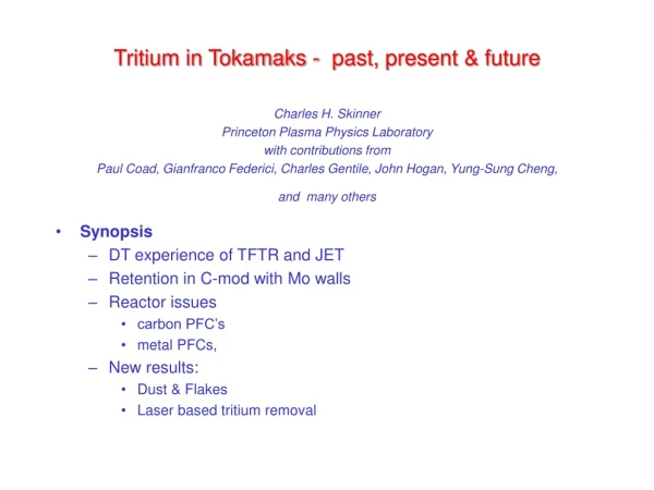
Tritium in Tokamaks - past, present & futureCharles H. SkinnerPrinceton Plasma Physics Laboratorywith contributions from Paul Coad, Gianfranco Federici, Charles Gentile, John Hogan, Yung-Sung Cheng, and many others • Synopsis • DT experience of TFTR and JET • Retention in C-mod with Mo walls • Reactor issues • carbon PFC’s • metal PFCs, • New results: • Dust & Flakes • Laser based tritium removal
TFTR 10 MW fusion power Limiter machine typical SOL parameters Ne ~ 0.1e19 - 1e19 m-3 Te ~ 200 eV - 600 eV JET 16 MW fusion power Divertor machine typical divertor parameters Ne ~ 10 e 19 m-3 Te ~ < 30 eV Tritium experience of TFTR & JET
Tritium retention TFTR: 3 run periods over 3.5 y 3.1 g 2.1 g 2.6 g ≈ 90% 51% 0.85 g (4/98) 16% (4/98) JET: DTE1, over 6 m 0.6 g34.4 g 11.5 g ≈40% 17% 4.2 g (7/98) 12% (7/98)6% (12/99) Total tritium injected, NBI gas puff Total tritium retained during DT operations Initial % retention during T puff fueling (wall saturation + isotope exchange) Longer term % retention including D only fueling (mostly co-deposition) Tritium remaining in torus Long term retention • Larger source of carbon (for co-deposition) in TFTR limiter • TFTR limiter conditioned to low D/C before T gas puffing. • D pulsing removed T from JET dynamic inventory leaving ~1/2 in co-deposits
Location of Tritium in TFTR Co-deposition, flaking, on bumper limiter at Bay K. Tritium released (Ci) by 1 hour, 500C bake of Bay K (L) tiles.
Location of TFTR Tritium inventory: • 1/3 tritium on bumper limiter, 2/3 on outboard wall • Remarkably good agreement between extrapolation from bakeout measurements and difference inventory (fueling less exhaust) and measurements at both PPPL and Savannah River.
Tritium retention in JET higher than expected • Flakes seen on louvres in divertor. • Tiles contain less tritium than expected. • Tiles 3 & 4 showed unexpectedly high bulk tritium concentrations • Remaining tritium believed to be in flakes in sub-divertor
Flakes and heavy deposits in JET Flakes from JET louvres at inner divertor Heavy deposits on JET inner divertor tile 4 .
Summary from TFTR & JET: • Tritium retention due to isotope exchange in dynamic wall inventory and co-deposition with eroded carbon. • TFTR had large source of eroded carbon from limiter for co-deposition. • Tritium retention in line with deuterium experience • Modeling shows high erosion / deposition of C and Li at limiter leading edges. • T retention high on leading edges, in line with predictions. • JET Tritium retention higher than expected from preliminary tritium expt. • JET used intensive T gas puffing which exchanged with D in wall. • Material eroded in main chamber flows into inner divertor. There, carbon is chemically sputtered and migrates to (cool) shadowed areas to form thick deposits with high D(plus T)/C • Retention measurements, surface analysis and modeling give consistent picture. But..... • Future DT power reactor needs retention fraction <~ 0.1% to be self sufficient in tritium. • Carbon plasma facing components are unacceptable for a DT power reactor.
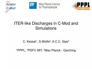
Retention in metal walled tokamaks • C-mod is lined with Mo tiles - there are no carbon PFC’s • Boronization used to reduce plasma impurities (carbon present at very low level) • Fuel is deuterium, nuclear reactions in plasma generate low levels of tritium. • Tile analysis by Wampler (SNL) showed most of D inventory implanted (not codeposited) on main chamber wall • Fraction of tritium produced that is retained is less than 0.002, 100x smaller than with carbon PFC’s • Use of metal PFC’s in reactors depends on minimising impurity transport and melt layer loss during disruptions. Alcator C-mod
Recent review:“Plasma Material Interactions in Current Tokamaks and their implications for Next-Step fusion reactors.” • recommend download from http://www.pppl.gov/pub_report/ • PPPL-3531/IPP-9/128 Preprint: January 2001, UC-70 • Highly relevant to aim of town meeting • Chapter 6 devoted to Future R&D priorities: Carbon PFCs Fork in the road: Metal PFCs
R&D issues for carbon PFCs Some key points: • Frequent replacements of PFCs needed due to ~10nm/s erosion • Flux dependence of chemical erosion yield and sticking coefficients of radicals still an open question. • SOL flows need to be better diagnosed and understood • Behavior of mixed materials uncertain • Disruption and ELM loads a major challenge issues include vapor shielding, brittle destruction.... • Tritium retention unsustainable in power reactors
R&D issues for metal PFC’s • Encouraging results from C-mod (Mo wall), and ASDEX (W-coated divertor plates and central column). • W ‘brush’ materials tested up to 20 MW/m2. but.... • Control of transport and MHD in alpha heated plasmas critical (core high–Z impurity levels detrimental to plasma performance even at ~10-5). • Disruption and ELM loads a major challenge • issues include melt layer loss, vapor shielding • Disruptions need to be very rare • High confinement without ELMs needed. • Data on neutron effects on tungsten sparse due to activation. • Public acceptance of handling/ disposal of activated tungsten
Common R&D issues • Minimization, control and accountancy of tritium inventory a critical issue. • Tritium needed in burning plasma is small fraction of total. • Fast regeneration of in-vessel cryopumps would help reduce inventory. • Efficient fueling reduced needed total tritium inventory and aids tritium self sufficiency. • Ar and Ne injection planned to control divertor detachment but.. • will become activated, making current tritium detectors unusable for exhaust stream - new detection technology needed. • Advanced plasma scenarios with high edge temperatures will result in severe erosion. • Wall conditioning e.g. boronization, over 1000 s pulses, an issue • Behavior of mixed materials uncertain • In-vessel dust diagnosis to demonstrate compliance with regulatory limits a major challenge • Tritium removal/decontamination in areas that require hands-on maintenance also challenging.
Dust and Flakes • All tokamaks generate dust. • Flake/dust production will inevitably increase with the increase in duty cycle in next-step devices with graphite plasma facing components. • Carbon tritide from tokamaks is toxic, radioactive and chemically reactive. - quantitive assessment is needed. • Just diagnosing how much dust is in existing machines is a major challenge Particles on TFTR vessel floor Flaking on TFTR limiter
TFTR dust analysis (collaboration with Y.S. Cheng, Lovlace Respiratory Research Institute) • Dust is respirable and can stay suspended in air for a long time • Count Mean Diameter (CMD) =1.25 µm • Geometric Standard Deviation (GSD) =1.74 µm • Currently NO standards for occupational exposure to tritiated graphite dust. • In vitro dissolution rate in simulated lung fluid: > 90% of tritium remained in particles after 110 d (HTO eliminated from body in 10 d) • ICRP modeling suggests occupational limit (DAC) is 4.4x lower than HTO - new techniques for real-time monitoring technology needed. • In vivo biological studies recommended Microscopic image of TFTR dust Particle size distribution 1.0 D N/NT /D log d 0.0 1.0 10.0 Project area diameter µm,
Tritium removal by Nd laser • Motivation • In TFTR several weeks were needed for tritium removal after only 10-15 min of cumulative DT plasmas • Future reactors need T removal rate >> retention rate • Heating is proven method to release tritium but heating vacuum vessel to required temperatures (~ 350 C) is expensive. • Present candidate process involves oxidation, requiring lengthy machine re-conditioning and expensive DTO processing • But • most tritium is codeposited on the surface • only surface needs to be heated. • Modelling indicates that exposure to ~multi-kw/cm2laser flux for ~ 10 ms heats a 50 micron surface layer up to 2,000 C enabling tritium release.
Heating releases tritium: Heating of co-deposited TFTR tile and C implanted with D (Causey et al.) 30 nsec laser pulse on 4 types of C, implanted with 1.5keV D (Keroack et al.)
Modeling of laser heat pulse: Heat flux necessary to attain a 400 -> 2,000 K surface temperature rise for different graphites. Temperature vs. time at different depths into pyrolitic perp. under 3,000 w/cm2 for 20 ms. Note: wide differences between carbon materials - no thermal coefficients available for co-deposited amorphous tritiated carbon.
1st results: TFTR DT tile before and after Nd laser exposure Cube cut from CFC tile KC17 2E before laser exposure size: 7/8” a side In chamber after exposure to Nd laser 2000 mm/s @ 40 W and 200 mm/s @ 6 W
Laser in action: Nd laser power only 6 w (300 w available) ~0.5mm focal spot, 200mm/sscanning across TFTR DT tile cube in air. Pyrometer views 0.7 mm area on DT codeposit on CFC tile on 2nd scan (temp.>2,300C on cube 3E) (pyrometer range 500 C - 2300 C)
Preliminary data on tritium released in first expt. • Surface tritium (measured with open wall ion chamber) decreased • from 51 µCi/cm2 before • to 14 µCi/cm2 after Nd laser exposure • 2.6 mCi released by Nd laser • 10.7 mCi released on exposure on baking at 500 C for 1 hour in air. • Non plasma facing surface on cube 3E heated to > 2300 C by Nd laser showed complete removal of surface tritium. • Powerful decontamination technique. • Need to optimize scan rate, laser power, laser focal spot size, investigate desorption processes, surface effects....
The Future ? - Voyager II • 3e7 J required to heat top 100 microns of 50 m2 divertor. - corresponds to output of 1kW laser for only 8 hours ! • Nd laser can be coupled via fiberoptic • Potential for oxygen free tritium release in operating tokamak • avoid deconditioning plasma facing surfaces • avoid HTO generation(HTO is 10,000x more hazardous than T2 and very expensive to reprocess)
Further reading: • “Studies of tritiated co-deposited layers in TFTR”J. Nucl. Mater. 266(1999) 941. PSI-14 J. Nucl. Mater in press • “Tritium Retention and Cleanup in JET” Fus. Eng. & Des. 47 (1999) 233 • “Long Term Retention of Deuterium and Tritium in Alcator C-mod”Proceedings of 18th Symposium on Fusion Energy, (1999) p.267. • “Tritium experience in large tokamaks: Application to ITER”Nuclear Fusion 39, 271, (1999) • “Plasma-material Interactions in Current Tokamaks and their Implications for Next-step Fusion Reactors.” PPPL-3531/IPP-9/128 Preprint: January 2001, UC-70 download from http://www.pppl.gov/pub_report/