Download
1 / 30
300 likes | 319 Views
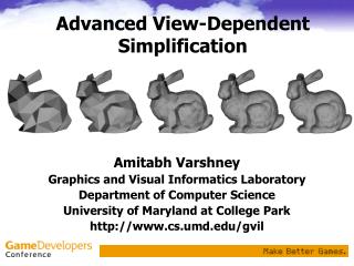
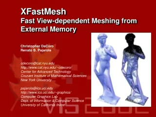
XFastMesh Fast View-dependent Meshing from External Memory. Christopher DeCoro Renato B. Pajarola. cdecoro@cat.nyu.edu http://www.cat.nyu.edu/~cdecoro/ Center for Advanced Technology Courant Institute of Mathematical Sciences New York University pajarola@ics.uci.edu

E N D
XFastMeshFast View-dependent Meshing from External Memory Christopher DeCoro Renato B. Pajarola cdecoro@cat.nyu.edu http://www.cat.nyu.edu/~cdecoro/ Center for Advanced Technology Courant Institute of Mathematical Sciences New York University pajarola@ics.uci.edu http://www.ics.uci.edu/~graphics/ Computer Graphics Lab Dept. of Information & Computer Science University of California Irvine
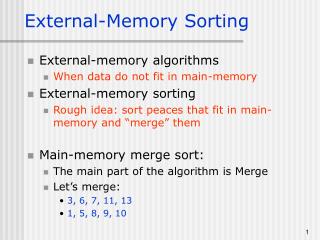
Talk Outline • Introduction • Motivation and applications • Related work • Background • External-memory structure • Main-memory structure • Experimental results • Future work
Motivation • Huge geometric models • Digital 3D scanners • Digital Michelangelo's David, 8M triangles • CAD, scientific visualization, GIS • Limited rendering performance • Graphics hardware accelerators can render a fixed amount of triangles in real-time • We can acquire huge models that far exceed the capability of graphics cards in the foreseeable future • Limited memory size • Current models can require more storage than we can afford to spend (or want to spend) • Multiresolution formats require additional space
Related Work • View-dependent mesh simplification • binary vertex trees [Xia et al. 96+] and [Hoppe 97+] • multi-triangulation [DeFloriani et a. 98+] • vertex clustering hierarchies [Luebke & Erikson 97] and [Schmalstieg & Schaufler 97] • FastMesh [Pajarola 01] • External-memory mesh simplification • El-Sana and Chiang [2001] • Prince [2000]
Background - Half-edges B B A Edge collapse A b b a a h.n.v h h h.v Vertex split c d d D D c C C • Represents mesh and simplification operations with half-edges and edge collapses / vertex splits • Three consecutive half-edges form a triangle • Each half-edge stores its reverse half-edge, and starting vertex • Half-edges allow for efficient local mesh update • Each vertex split introduces 1 vertex and 2 triangle faces
h4 h5 h14 Active front F expanded h3 h2 h9 h10 h12 h6 collapsed h1 h11 h13 h8 h7 Background -Multiresolution Hierarchy expanded vertex splits collapsed edges and faces Half-edge collapse hierarchy • Uses a hierarchy of half-edge-collapse operations • Each node corresponds to a split/collapse • Level of detail represented as front through hierarchy • Detail increases as the front descends the tree
Background - Basic Simplification Criteria • Out-of-frustum Simplification • Back-face Simplification
Background – Heuristic Simplification Criteria • Screen-projection Simplification • Normal-angle Deviation • Silhouette Preservation
h1 h3 Background - LOD parameters • Bounding spheres • minimal sphere enclosing all affected triangles (vertices) and spheres of child nodes
h1 h3 h4 h2 Background - LOD parameters • Bounding spheres • minimal sphere enclosing all affected triangles (vertices) and spheres of child nodes • Bounding normal cones • minimal bounding cone around vertex normal enclosing all normal directions of subtree
Talk Outline • Introduction • External-memory structure • Overview • Initial mesh • Detail blocks • Auxiliary data • Data file construction • Main-memory structure • Experimental results • Future work
External Memory Structure – Overview • Base mesh stored as-is in external storage • Loaded at run-time, kept resident during execution • Detail stored as discrete blocks • Similar in structure to a B-tree (high-degree nodes) • Links within a block represented implicitly • All faces/vertices/half-edges given unique ID • ID is used to determine the block number • Block number is used to determine disk location
Detail blocks • Edge-collapse trees are divided into blocks • Assumes full subtrees • Forms “block tree” • High-degree nodes, similar to B-tree • Blocks efficiently encode detail • Intra-block links represented implicitly
Detail blocks – Geometry • Form disc-like regions on the surface • Therefore, block nodes are located spatially close together • Similar positions and orientation • Lower level blocks form smaller disks • Parent discs (left) encompass child discs (right)
Detail Blocks - Contents • Information is stored for each existing node • Vertex, normal coordinates • Bounding sphere radius, bounding cone angle • Global ordering • Used for fold-over prevention • Four Adjacent half-edges • Connectivity; used to place new edges into mesh • Stores connectivity to other blocks • ID of parent node (locates block and node) • ID of all child nodes • Flags • Indicates number of nodes present
Detail Blocks - Packing • High-degree trees will have many leaves • As blocks store complete subtrees, leaf blocks will be non-full • Leaf blocks do not need child pointers • Blocks are packed to remove wasted space • Only nodes that exist are stored in block • Flags indicate which blocks are available • Maintains complete subtree structure • Child pointers stored only for non-leaf nodes • Also indicated by flag
Auxiliary Data • Header • Fixed sized header indicating locations of other fields • Initial Mesh • Base mesh M0 stored explicitly on disk, loaded at start time • Block Index • For given block b, stores disk offset of b • Required because packing scheme results in blocks with varying sizes • Index itself can be entirely loaded at startup, or accessed through memory-mapping • Root Block List • Lists which blocks contain root nodes of the hierarchy • Root blocks are loaded at start time and kept resident
Talk Outline • Introduction • External-memory structure • Main-memory structure • Overview • Block loading • Block deletion • Experimental results • Future work
Main-memory Structure - Overview • Block Directory • Points to all loaded blocks • Similar to a page table • High bits of ID represent block • Low bits of ID represents offset in block • Time Priority Queue • Min-queue that stores blocks by least recently used • Used for caching blocks
Tree Node • Mesh • Stores additional vertex, normal coordinates • Six half-edges, representing two faces introduced by split • Trees • Links to merge tree nodes • Links to block tree nodes • Timestamp • Simplification parameters
Block Loading • Case 1: Front moves below “frontier” of loaded blocks • Frontier: lowest point in the hierarchy for which blocks are loaded • Given block ID, lookup disk address in block index, read from disk • Inflate block from disk format; enter into directory, attach to tree
Block Loading • Case 2: Forced split requires load of arbitrary block • Update operations that can be required to maintain mesh; • results from edge collapses • From split edge ID, determine block ID; read block • Use parent ID to load parent block • Repeat until all blocks are connected into the hierarchy
Block Deletion • Caching is required for acceptable performance • Once user-specified quota is reached, blocks will be deleted • Least-recently-used blocks are removed first • Marked as unused when front moves above root node of block • Maintains a priority-queue to determine LRU blocks
Talk outline • Introduction • External-memory structure • Main-memory structure • Experimental results • Storage cost • Run-time performance • Examples • Future work
Storage cost • Cost of data file measured on disk • Less than 30 bytes/tri • Compares to our original format (about equal) • More efficient than previous external methods
Run-time performance Sun 450MHz UltraSPARC-II CPU, Expert3D PCI graphics • Results shown are average time per frame • Block load time is generally dominated by rendering • Block load time also tends to be much less than the view-dependent operations • Through caching, load time tends to decrease as a percentage of frame over time
More examples • Upper row displays view from user’s perspective • Lower row shows same image from outside view (represented as yellow pyramid) • Threshold adjusted to achieve constant 5 frames / second • Between 50 K – 67 K triangles per frame
Future work • Out-of-core Preprocess • Would allow more flexibility in creating models • Asynchronous disk access • Parrallelize time spent reading from disk • Pre-fetch • One solution could be based on predicting path of camera movement • Another could base prefetching based on rate of change in the front • Geometry Compression • Allows more information transferred through disk bottleneck • Tradeoff between processor speed vs. disk speed/storage
Conclusion • Straight-forward approach to external-memory meshing can be successful, if implemented efficiently • Hierarchy broken into blocks • Minimal transformations to hierarchy required • Synchronous disk access • Disk access overhead, when blocks are cached, can be minimized • Synchronous access does not present excessive overhead • History-based Caching • Least-recently used caching scheme dramatically reduces disk accesses • No need to attempt prediction of detail required in upcoming frames