Main Memory
520 likes | 546 Views
This lecture notes-based article discusses the organization and optimization techniques of main memory, including DRAM chips, interleaving, banking, memory controller design, and virtual memory.

Main Memory
E N D
Presentation Transcript
Main Memory Prof. Mikko H. Lipasti University of Wisconsin-Madison ECE/CS 752 Spring 2016 Lecture notes based on notes by Jim Smith and Mark Hill Updated by Mikko Lipasti
Readings • Discuss in class: • Read Sec. 1, skim Sec. 2, read Sec. 3: Bruce Jacob, “The Memory System: You Can't Avoid It, You Can't Ignore It, You Can't Fake It,” Synthesis Lectures on Computer Architecture 2009 4:1, 1-77. • Review #2 due 3/30/2016: Steven Pelley, Peter Chen, and Thomas Wenisch, "Memory Persistency," Proc. ISCA 2014, June 2014 Online PDF
Summary: Main Memory • DRAM chips • Memory organization • Interleaving • Banking • Memory controller design • Hybrid Memory Cube • Phase Change Memory (reading) • Virtual memory • TLBs • Interaction of caches and virtual memory (Baer et al.) • Large pages, virtualization
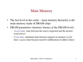
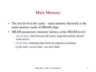
DRAM Chip Organization • Optimized for density, not speed • Data stored as charge in capacitor • Discharge on reads => destructive reads • Charge leaks over time • refresh every 64ms • Cycle time roughly twice access time • Need to prechargebitlines before access
DRAM Chip Organization • Current generation DRAM • 8Gbit @25nm • 266 MHz synchronous interface • Data clock 4x (1066MHz), double-data rate so 2133 MT/s • Address pins are time-multiplexed • Row address strobe (RAS) • Column address strobe (CAS)
DRAM Chip Organization • New RAS results in: • Bitlineprecharge • Row decode, sense • Row buffer write (up to 8K) • New CAS • Read from row buffer • Much faster (3x) • Streaming row accesses desirable
Simple Main Memory • Consider these parameters: • 10 cycles to send address • 60 cycles to access each word • 10 cycle to send word back • Miss penalty for a 4-word block • (10 + 60 + 10) x 4 = 320 • How can we speed this up?
Wider(Parallel) Main Memory • Make memory wider • Read out all words in parallel • Memory parameters • 10 cycle to send address • 60 to access a double word • 10 cycle to send it back • Miss penalty for 4-word block: 2x(10+60+10) = 160 • Costs • Wider bus • Larger minimum expansion unit (e.g. paired DIMMs)
Interleaved Main Memory • Break memory into M banks • Word A is in A mod M at A div M • Banks can operate concurrently and independently Bank 0 • Each bank has • Private address lines • Private data lines • Private control lines (read/write) Bank 1 Byte in Word Word in Doubleword Bank Bank2 Doubleword in bank Bank 3
Interleaved Memory Examples Ai = address to bank i Ti = data transfer • Unit Stride: • Stride 3:
Interleaved Memory Summary • Parallel memory adequate for sequential accesses • Load cache block: multiple sequential words • Good for writeback caches • Banking useful otherwise • If many banks, choose a prime number • Can also do both • Within each bank: parallel memory path • Across banks • Can support multiple concurrent cache accesses (nonblocking)
DDR SDRAM Control • Raise level of abstraction: commands • Activate row Read row into row buffer • Column access Read data from addressed row • Bank Precharge Get ready for new row access
DDR SDRAM Timing • Read access
Constructing a Memory System • Combine chips in parallel to increase access width • E.g. 8 8-bit wide DRAMs for a 64-bit parallel access • DIMM – Dual Inline Memory Module • Combine DIMMs to form multiple ranks • Attach a number of DIMMs to a memory channel • Memory Controller manages a channel (or two lock-step channels) • Interleave patterns: • Rank, Row, Bank, Column, [byte] • Row, Rank, Bank, Column, [byte] • Better dispersion of addresses • Works better with power-of-two ranks
Memory Controllers • Contains buffering • In both directions • Schedulers manage resources • Channel and banks
Resource Scheduling • An interesting optimization problem • Example: • Precharge: 3 cycles • Row activate: 3 cycles • Column access: 1 cycle • FR-FCFS: 20 cycles • StrictFIFO: 56 cycles
DDR SDRAM Policies • Goal: try to maximize requests to an open row (page) • Close row policy • Always close row, hides precharge penalty • Lost opportunity if next access to same row • Open row policy • Leave row open • If an access to a different row, then penalty for precharge • Also performance issues related to rank interleaving • Better dispersion of addresses
Memory Scheduling Contest • http://www.cs.utah.edu/~rajeev/jwac12/ • Clean, simple, infrastructure • Traces provided • Very easy to make fair comparisons • Comes with 6 schedulers • Also targets power-down modes (not just page open/close scheduling) • Three tracks: • Delay (or Performance), • Energy-Delay Product (EDP) • Performance-Fairness Product (PFP)
Future: Hybrid Memory Cube • Micron proposal [Pawlowski, Hot Chips 11] • www.hybridmemorycube.org
Hybrid Memory Cube MCM • Micron proposal [Pawlowski, Hot Chips 11] • www.hybridmemorycube.org
Network of DRAM • Traditional DRAM: star topology • HMC: mesh, etc. are feasible
Hybrid Memory Cube • High-speed logic segregated in chip stack • 3D TSV for bandwidth
Future: Resistive memory • PCM: store bit in phase state of material • Alternatives: • Memristor (HP Labs) • STT-MRAM • Nonvolatile • Dense: crosspoint architecture (no access device) • Relatively fast for read • Very slow for write (also high power) • Write endurance often limited • Write leveling (also done for flash) • Avoid redundant writes (read, cmp, write) • Fix individual bit errors (write, read, cmp, fix)
Main Memory and Virtual Memory • Use of virtual memory • Main memory becomes another level in the memory hierarchy • Enables programs with address space or working set that exceed physically available memory • No need for programmer to manage overlays, etc. • Sparse use of large address space is OK • Allows multiple users or programs to timeshare limited amount of physical memory space and address space • Bottom line: efficient use of expensive resource, and ease of programming
Virtual Memory • Enables • Use more memory than system has • Think program is only one running • Don’t have to manage address space usage across programs • E.g. think it always starts at address 0x0 • Memory protection • Each program has private VA space: no-one else can clobber it • Better performance • Start running a large program before all of it has been loaded from disk
Virtual Memory – Placement • Main memory managed in larger blocks • Page size typically 4K – 16K • Fully flexible placement; fully associative • Operating system manages placement • Indirection through page table • Maintain mapping between: • Virtual address (seen by programmer) • Physical address (seen by main memory)
Virtual Memory – Placement • Fully associative implies expensive lookup? • In caches, yes: check multiple tags in parallel • In virtual memory, expensive lookup is avoided by using a level of indirection • Lookup table or hash table • Called a page table
Virtual Memory – Identification • Similar to cache tag array • Page table entry contains VA, PA, dirty bit • Virtual address: • Matches programmer view; based on register values • Can be the same for multiple programs sharing same system, without conflicts • Physical address: • Invisible to programmer, managed by O/S • Created/deleted on demand basis, can change
Virtual Memory – Replacement • Similar to caches: • FIFO • LRU; overhead too high • Approximated with reference bit checks • “Clock algorithm” intermittently clears all bits • Random • O/S decides, manages • CS537
Virtual Memory – Write Policy • Write back • Disks are too slow to write through • Page table maintains dirty bit • Hardware must set dirty bit on first write • O/S checks dirty bit on eviction • Dirty pages written to backing store • Disk write, 10+ ms
Virtual Memory Implementation • Caches have fixed policies, hardware FSM for control, pipeline stall • VM has very different miss penalties • Remember disks are 10+ ms! • Hence engineered differently
Page Faults • A virtual memory miss is a page fault • Physical memory location does not exist • Exception is raised, save PC • Invoke OS page fault handler • Find a physical page (possibly evict) • Initiate fetch from disk • Switch to other task that is ready to run • Interrupt when disk access complete • Restart original instruction • Why use O/S and not hardware FSM?
Address Translation • O/S and hardware communicate via PTE • How do we find a PTE? • &PTE = PTBR + page number * sizeof(PTE) • PTBR is private for each program • Context switch replaces PTBR contents
Address Translation Virtual Page Number Offset PTBR + D VA PA
Page Table Size • How big is page table? • 232 / 4K * 4B = 4M per program (!) • Much worse for 64-bit machines • To make it smaller • Use limit register(s) • If VA exceeds limit, invoke O/S to grow region • Use a multi-level page table • Make the page table pageable (use VM)
Multilevel Page Table Offset PTBR + + +
Hashed Page Table • Use a hash table or inverted page table • PT contains an entry for each real address • Instead of entry for every virtual address • Entry is found by hashing VA • Oversize PT to reduce collisions: #PTE = 4 x (#phys. pages)
Hashed Page Table Virtual Page Number Offset Hash PTBR PTE0 PTE1 PTE2 PTE3
High-Performance VM • VA translation • Additional memory reference to PTE • Each instruction fetch/load/store now 2 memory references • Or more, with multilevel table or hash collisions • Even if PTE are cached, still slow • Hence, use special-purpose cache for PTEs • Called TLB (translation lookaside buffer) • Caches PTE entries • Exploits temporal and spatial locality (just a cache)
Translation Lookaside Buffer Index Tag • Set associative (a) or fully associative (b) • Both widely employed
Interaction of TLB and Cache • Serial lookup: first TLB then D-cache • Excessive cycle time
Virtually Indexed Physically Tagged L1 • Parallel lookup of TLB and cache • Faster cycle time • Index bits must be untranslated • Restricts size of n-associative cache to n x (virtual page size) • E.g. 4-way SA cache with 4KB pages max. size is 16KB
Virtual Memory Protection • Each process/program has private virtual address space • Automatically protected from rogue programs • Sharing is possible, necessary, desirable • Avoid copying, staleness issues, etc. • Sharing in a controlled manner • Grant specific permissions • Read • Write • Execute • Any combination
Protection • Process model • Privileged kernel • Independent user processes • Privileges vs. policy • Architecture provided primitives • OS implements policy • Problems arise when h/w implements policy • Separate policy from mechanism!
Protection Primitives • User vs kernel • at least one privileged mode • usually implemented as mode bits • How do we switch to kernel mode? • Protected “gates” or system calls • Change mode and continue at pre-determined address • Hardware to compare mode bits to access rights • Only access certain resources in kernel mode • E.g. modify page mappings
Protection Primitives • Base and bounds • Privileged registers base <= address <= bounds • Segmentation • Multiple base and bound registers • Protection bits for each segment • Page-level protection (most widely used) • Protection bits in page entry table • Cache them in TLB for speed
VM Sharing • Share memory locations by: • Map shared physical location into both address spaces: • E.g. PA 0xC00DA becomes: • VA 0x2D000DA for process 0 • VA 0x4D000DA for process 1 • Either process can read/write shared location • However, causes synonym problem
VA Synonyms • Virtually-addressed caches are desirable • No need to translate VA to PA before cache lookup • Faster hit time, translate only on misses • However, VA synonyms cause problems • Can end up with two copies of same physical line • Causes coherence problems [Wang, Baer reading] • Solutions: • Flush caches/TLBs on context switch • Extend cache tags to include PID • Effectively a shared VA space (PID becomes part of address) • Enforce global shared VA space (PowerPC) • Requires another level of addressing (EA->VA->PA)