Tim Marker
Discussion of Burner Heat Flux Mapping for Proposed Insulation Burnthrough Test Standard. Tim Marker. FAA Technical Center. Heat Flux Mapping of Burner Flame. Purpose: To produce a burner flame profile to determine if the high

Tim Marker
E N D
Presentation Transcript
Discussion of Burner Heat Flux Mapping for Proposed Insulation Burnthrough Test Standard Tim Marker FAA Technical Center
Heat Flux Mapping of Burner Flame Purpose: To produce a burner flame profile to determine if the high heat flux area(s) are in the same location as the current location used during calibration. The flame profile is a useful tool in making lab-to-lab comparisons. Methodology: Use existing heat flux transducer (calorimeter) to measure the heat flux at a variety of pre-set locations. ____________________
Conclusions of Mapping (2nd time) Standardization of intake system likely reduced lab-to-lab differences Elimination of “highly irregular” flame profiles Full analysis of progress very difficult: Small data set (only 5 of 9 labs reporting) Standardized mapping procedure not fully adhered to (2 of 5 mapped differently)
Future Considerations Standardization of calorimeter mounting block size/type Use the 6- by 12-inch marinite block specified in proposed Rule, Use another agreed-to size/type of mounting block Standardization of initial temperature of calorimeter block Thermocouple imbedded into mounting block surface provides accurate initial temperature Heat soak the calorimeter prior to start of mapping Revised data collection procedure Continuous collection of all 21 data points without shutting burner off
Heat Flux Transducer Sample Holder Used for Continuous Data Collection
Heat Flux Transducer Sample Holder Used for Continuous Data Collection
Heat Flux Transducer Sample Holder Used for Continuous Data Collection
Heat Flux Transducer Sample Holder Used for Continuous Data Collection Insufficient board material between holes Crack!
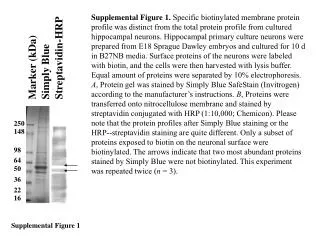
Initial Result Using Marinite Board Marinite-inorganic calcium silicate board
Second Result Using Zircal-95 Board Zircal 95-high density calcium silicate hydrate mix
Conclusions Continuous mapping of burner flame using pre-drilled sample board/heat flux transducer very difficult. Future of HF mapping Original mapping method, with sufficient cooling time between locations. Imbedded thermocouple placed in mapping block to ensure appropriate start time. Continuous mapping using thicker/stronger board material, with sufficient protection for operator. Alternative approach using IR camera.
Burnthrough Task Group Report Tim Marker FAA Technical Center
Revised Burner Mapping Procedure 2 minute warm-up + 1 minute soak, 10 second data collection Position 1
Revised Burner Mapping Procedure Move entire board 1 inch, 10 second data collection Position 2
Revised Burner Mapping Procedure Move entire board 1 inch, 10 second data collection Position 3
Revised Burner Mapping Procedure Move entire board 1 inch, 10 second data collection Position 4
Revised Burner Mapping Procedure Move entire board 1 inch, 10 second data collection Position 5
Revised Burner Mapping Procedure Move entire board 1 inch, 10 second data collection Position 6
Revised Burner Mapping Procedure Move entire board 1 inch, 10 second data collection Position 7
Revised Burner Mapping Procedure Move entire board back to 1st position, 10 second data collection Position 1
Revised Burner Mapping Procedure Drop entire board down 1 inch, repeat process Position 8
Revised Burner Mapping Procedure Position 9
Revised Burner Mapping Procedure Position 10
Revised Burner Mapping Procedure Position 11
Summary of New Mapping Process FAATC will draft up detailed drawings of new mapping board, including details such as material type, thickness, density, etc. Individual labs will be responsible for constructing their own mapping board. International Aero will continue its development of the IR mapping device, and a comparison of the 2 methods can be made prior to the next meeting.