Download
1 / 30
310 likes | 786 Views
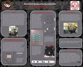
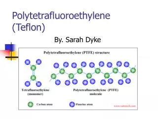
Determination of Light Elements by Rutherford Backscattering Technique on Teflon Filters. Presented by Jaspinder P. Singh University of California Crocker Nuclear Laboratory Davis, California. Contents. What Is Rutherford Backscattering? RBS & PESA Analysis Spectrums

E N D
Determination of Light Elements by Rutherford Backscattering Technique on Teflon Filters Presented by Jaspinder P. Singh University of California Crocker Nuclear Laboratory Davis, California
Contents • What Is Rutherford Backscattering? • RBS & PESA Analysis Spectrums • Peak Integration Methods • What Can the Integrated Counts Tell Us? • Relationships in RBS Analysis • Experimental Setup • Procedure for Blank Subtraction • Results • Conclusions & Works In Progress
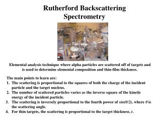
What Is Rutherford Backscattering? Rutherford Backscattering (RBS) is an analytical technique in which a high energy beam of low mass ions are directed at a sample. Particles which scatter from the sample are collected in a detector placed at close to a 180 degree angle. Because the amount of energy transferred to the sample atom depends on the ratio of masses between the ion and the sample atom, the chemical composition of the sample can be determined from measuring the energy of scattered ions.
What Is Rutherford Backscattering? RBS can also be used to perform a depth profile of the sample if the incident ion doesn’t hit a sample atom at the surface, but one further in. Proton Elastic Scattering (PESA) is an analytical technique based on the same principles as RBS, except with the detector placed for non-backscattered particles.
RBS Analysis Spectrums + t 2000 X θ1 θ θ2 1000 Counts Channel Ω Detector
Peak Integration Methods For clearly separated peaks, summing the counts in a range of channels can by done simply with a spreadsheet software. However, overlapping peaks or high background noise can make summing unreliable. A different method of integration must then be used.
Peak Integration Methods This Hydrogen peak barely escapes the background noise. Thus, a summation of counts in its channel range would yield inaccurate data for its true area.
Peak Integration Methods The Hydrogen peak can be interpreted without interference from the background using, in this case, a Gaussian curve. What was once noisy and chaotic is translated into a smooth and distinct peak.
What Can The Integrated Counts Tell Us? In thin films, the integrated counts in the peak comes from scattering from the ith element, and reveal the amount of atoms of i in the film. Because the amount of energy transferred to the sample atom depends on the ratio of masses between the ion and the sample atom, the chemical composition of the sample can be determined from measuring the energy of scattered ions.
Relationships in RBS Analysis From the detector solid angle Ω, the integrated peak count Ai for Q incident ions, and the cross section σi(E,θ), the areal density (Nt)i can be determined.
Relationships in RBS Analysis The Rutherford cross-section σR(E,θ) is calculable as well, with the knowledge of the atomic numbers of the incident and target ions (Z1 and Z2, respectively).
Relationships in RBS Analysis The integrated counts can be used in conjunction with the cross-section and other known values to determine, for example, the amount of protons in the run or the thickness of the film.
Relationships in RBS Analysis The ratio between the integrated counts of two elements in a multi-element film can reveal the stoichiometric relationship of the elements. The constants cancel out.
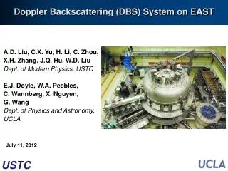
Experimental Setup For the determination of light elements in Teflon filters, we used: • A 4.5 MeV proton beam from 76-inch Crocker Nuclear Laboratory (CNL) cyclotron at the University of California, Davis. • A scattering chamber from ORTEC series 2800. • A surface barrier detector (Si) placed at 150 degree to the beam axis and 170mm from the center of the scattering chamber. • A detector thickness that will stop the 4.5 MeV proton beam with a resolution of 25 KeV.
Procedure for Blank Subtraction Consider an unloaded Teflon Filter (CF2).
Procedure for Blank Subtraction C12(p,p)C12 F19(p,p)F19 There is a distinct carbon peak and three fluorine energy states
Procedure for Blank Subtraction C12(p,p)C12 F19(p,p)F19 C12(p,p)C12 F19(p,p)F19 That Teflon filter is then loaded with elemental carbon (graphite) in a re-suspension chamber.
Procedure for Blank Subtraction C12(p,p)C12 Af,l F19(p,p)F19 Af,ul C12(p,p)C12 F19(p,p)F19 Although both filters are the same, there could be differences in the time length of an experimental run. Therefore, the loaded filter is normalized to the unloaded filter by the amplitude of the fluorine ground state.
Procedure for Blank Subtraction C12(p,p)C12 F19(p,p)F19 There is a little more counts in the loaded filter near the fluorine ground state. This is due to the presence of oxygen.
Procedure for Blank Subtraction C12(p,p)C12 O16(p,p)O16 By taking the difference between the loaded Teflon and the unloaded Teflon, we are left with distinct carbon and oxygen peaks. Using the methods previously described, the areas of these peaks can yield the amount of the element loaded.
Results Direct Method Another example of a Teflon filter before and after loaded elemental carbon (graphite) using a re-suspension chamber. The difference in weight and the area of the deposit gave an areal density of 74.84 µg/cm². The value extracted from RBS was 69±6 µg/cm².
Simulated Method Mesa Verda spectrum with the calculation is made using SIMNRA for a Teflon sample and normalized to the fluorine peak.
Indirect Method Spectrum of a Mesa Verde Teflon filter compared with the spectrum of the blank Teflon filter. To extract the oxygen is straightforward. Fluorine has two excited states that can be excited with 4.5 MeV protons.
The oxygen implied from IMPROVE measurement is calculated from the mass concentration of sulfur and soil elements (Si;Al;Ca;Ti;Fe) in the oxides form. SOIL=2.2*[Al]+2.49*[Si]+1.63*[Ca]+2.42*[Fe]+1.94[Ti]
Tallgrass Prairie National Preserve, Kansas Everglades National Park, Florida (Saturday) Lava Beds National Park, California Everglades National Park, Florida (Monday)
Conclusions • Proton Rutherford Back Scattering analysis has been used to measure carbon and oxygen on Teflon filters. • We cannot measure nitrogen at this time because we do not have a suitable standard. • The method shows promise to extend the Crocker Nuclear laboratory’s analytical techniques. • Further development is needed and will be pursued in the coming months.