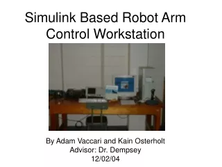
Download
1 / 37
430 likes | 2.27k Views
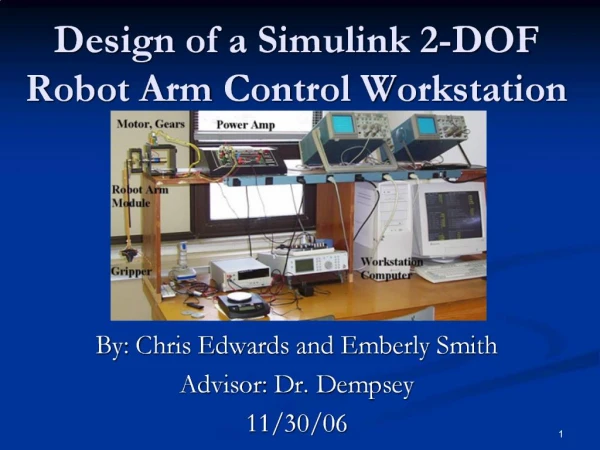
Design of a Simulink 2-DOF Robot Arm Control Workstation. By: Chris Edwards and Emberly Smith Advisor: Dr. Dempsey 3/1/07. Presentation Outline. Project Summary Previous Work Project Goals Functional Description, Requirements, and _ Specifications Overall Block Diagram and Subsystems

E N D
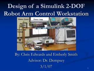
Design of a Simulink 2-DOF Robot Arm Control Workstation By: Chris Edwards and Emberly Smith Advisor: Dr. Dempsey 3/1/07
Presentation Outline Project Summary Previous Work Project Goals Functional Description, Requirements, and _Specifications Overall Block Diagram and Subsystems Controllers Equipment and Parts List Project Schedule GUI VR Workstation SimMechanics Modeling Remaining Objectives Questions and Discussion
Project Summary 2-DOF robot arm control __workstation Designed in Simulink __environment Mimics Quansar workstation Controller design
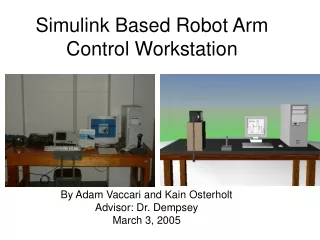
Vaccari and Osterholt’s Project Achievements • Modeling the robot arm in SimMechanics Toolbox • Designing closed-loop controllers • Real time visualization using the Virtual Reality __Toolbox • Implementing force feedback joystick control • Note: Non-inverting configuration was used with no load. Previous Work
Primary Project Goals • Add rotary flexible joint to the existing system model • Validate new model through experimental results • System ID for designing controllers • Design closed-loop controllers for 2-DOF robot arm • Single-loop position controller • Double-loop position/velocity controller • Feed-forward controller • Make additions to previous virtual reality workstation
Secondary Project Goals • Design advanced controller for the 2-DOF robot arm • Investigate different robot arm configurations • Level • Inverted • Non-inverted
Functional Description Mass-Damper-Spring System • Mass • Arm • Gripper • Load • Damper • Friction will act as the damper • Spring • Springs attach the robot arm to the base
Presentation Outline Project Summary Previous Work Project Goals Functional Description, Requirements, and _Specifications Overall Block Diagram and Subsystems Controllers Equipment and Parts List Project Schedule GUI VR Workstation SimMechanics Modeling Remaining Objectives Questions and Discussion
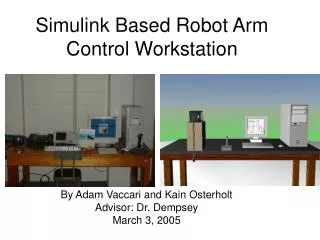
Equipment and Parts List Quansar Workstation Wingman Attack 2 Joystick Software SimMechanics Simulink Guide Virtual Reality Toolbox
Progress Completed the Model for the 1-DOF Level _Arm Configuration Finished Basic Layout for GUI Developed a Basic Understanding of VR __Workstation and made adjustments Currently in the Process of Adding the Rotary _Flexible Joint into the SimMechanics Model
Presentation Outline Project Summary Previous Work Project Goals Functional Description, Requirements, and _Specifications Overall Block Diagram and Subsystems Controllers Equipment and Parts List Project Schedule GUI VR Workstation SimMechanics Modeling Remaining Objectives Questions and Discussion
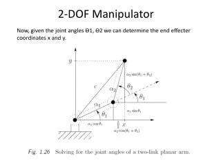
Coordinate Systems X Y Z World Non-Inverted Arm Configuration Gravity Vector [0, 0, 9.8] m/s²
Coordinate Systems Y Z World X Level Arm Configuration Gravity Vector [0, -9.8, 0] m/s²
Rotary Joint with Springs Body Anchor Points: Both A r: 3.18 cm d: 3.18 cm Arm Anchor Point: 3 R = 7.60 cm Spring Type: 1 Length: 2.54 cm Spring Constant: 220 N/m
Remaining Modeling Objectives • Measure Friction in Rotary Joint from Experimental Workstation • Add Negative Feedback Path for Friction • Add New Sensors for Robot Arm Position and Velocity • Test and Verify SimMechanics Model