Download
1 / 29
290 likes | 438 Views
The Unified Modeling Language (UML) integrates traditional modeling approaches, aiding developers in creating visual models for software engineering. Developed by industry leaders, UML standardizes various diagrams including class, object, component, use case, sequence, and others to represent structural and behavioral aspects of systems. Goals include providing an extensible language, promoting object-oriented tools, and facilitating model exchange. UML supports various perspectives such as conceptual, specification, and implementation, ultimately encouraging an organized approach to software design.

E N D
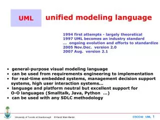
4.1. Motivation • The Unified Modeling Language tries to integrate older approaches • Developed by Rational (CASE tool) • they hired Booch, Rumbaugh, Jacobsen • Standardized at version 1.1 by the OMG (Object Management Group) • Supported by almost all OO CASE tools … but with some limitations … • Currently it is at version 1.4 (OMG working on 2.0) CPSC 333: Foundations of Software Engineering J. Denzinger
Goals of UML • Provide users with ready-to-use, expressive visual modeling language to develop and exchange meaningful models. • Provide extensibility and specialization mechanisms to extend the core concepts. • Be independent of particular languages and processes. • Provide formal basis for understanding the modeling language. • Encourage the growth of the OO tools market. • Support higher-level development concepts such as collaborations, frameworks, patterns and components. • Integrate best practices. CPSC 333: Foundations of Software Engineering J. Denzinger
UML has 9 kinds of diagrams • Class Diagram • Object Diagram • Component Diagram • Deployment Diagram • Use Case Diagram • Sequence Diagram • Collaboration Diagram • Statechart Diagram • Activity Diagram Structural Diagrams Behavioral Diagrams CPSC 333: Foundations of Software Engineering J. Denzinger
4.2. Structural diagrams4.2.1. Class diagram • Central for OO modeling • Shows static structure of the system • Types (!) of objects • Static relationships (see next lecture) • Association (e.g.: a company has many employees) • Generalization (subtypes) (e.g.: an employee is a kind of person) • Dependencies (e.g.: a company is using trucks to ship products) CPSC 333: Foundations of Software Engineering J. Denzinger
Class • Set of objects • Defines • name • attributes(optional: type optional: initial value) • operations Task startDate: Date = default endDate: Date name setStartDate (d : Date) setEndDate (d : Date) getDuration () : Date CPSC 333: Foundations of Software Engineering J. Denzinger
Class diagram example association Actuator startUp( ) shutDown( ) generalization Light Heater Cooler Temperature off( ) 1 1 on( ) aggregation 0..* 1 1 1 Environmental Controller SystemLog define_climate( ) display( ) CPSC 333: Foundations of Software Engineering J. Denzinger terminate_climate( ) recordEvent( )
Three Perspectives We can look at classes from these perspectives: • Conceptual (OOAnalysis) • Shows concepts of the domain • Should be independent from implementation • Specification (OODesign) • General structure of the running system • Interfaces of software (types, not classes) • Often: Best perspective • Implementation (OOProgramming) • Structure of the implementation (classes) • Most often used Try to draw from a clear, single perspective CPSC 333: Foundations of Software Engineering J. Denzinger
Attributes • Conceptual: Indicates that customer have names • Specification: Customer can tell you the name and set it(short for get/set methods) • Implementation: An instance variable is available Customer name address creditRating CPSC 333: Foundations of Software Engineering J. Denzinger
Operations • Services that a class knows to carry out • Correspond to messages of the class (or IF) • Conceptual level • principal responsibilities • Specification level • public messages = interface of the class • Normally: Don’t show operations that manipulate attributes CPSC 333: Foundations of Software Engineering J. Denzinger
UML syntax for operations visibility name (parameter list) : return-type-expression + assignAgent (a : Agent) : Boolean • visibility: public (+), protected (#), private (-) • Interpretation is language dependent • Not needed on conceptual level • name: string • parameter list: arguments (syntax as in attributes) • return-type-expression: language-dependent specification CPSC 333: Foundations of Software Engineering J. Denzinger
number : String Operations vs. Responsibilities UML 1.3 Specific (similar to CRC Cards) • Conceptual: Operations should specify responsibilities, not IF, e.g.: • The Customer specifies the Orders • The Orders list the Customer Order dateReceived Customer isPrepaid name address price : Money * 1 Responsibilities - specifies orders Responsibilities - lists the customer CPSC 333: Foundations of Software Engineering J. Denzinger
Class versus type • Type • protocol understood by an object • set of operations that are used • Class • implementation oriented construct • implements one or more types • In Java a type is an interface, in C++ a type is an abstract class • UML 1.3 has the <<interface>> stereotype and the lollipop CPSC 333: Foundations of Software Engineering J. Denzinger
<<interface>>DataInput close() Interfaces in UML (1) • Stereotype <<interface>> InputStream{abstract} OrderReader Dependency Generalization DataInputStream Realization CPSC 333: Foundations of Software Engineering J. Denzinger
Interfaces in UML (2) Lollipops (“short-hand notation”) DataInput OrderReader Interface DataInputStream Dependency CPSC 333: Foundations of Software Engineering J. Denzinger
4.2.2. Systems and subsystems System Design CPSC 333: Foundations of Software Engineering J. Denzinger
request for alarm notification periodic check-in require for configuration update Systems and Sub-Systems Control Sensor request for status panel subsystem test status subsystem request for system status specification of type of alarm periodic status check Central communication subsystem CPSC 333: Foundations of Software Engineering J. Denzinger
How to break a system into smaller subsystems? • Roman principle: Divide & conquer • Split up a large system into manageable parts • In structured methods: functional decomposition • In OO: Group classes into higher level units Packages (conceptual; at development time) Components (physical; at run time) CPSC 333: Foundations of Software Engineering J. Denzinger
ResourcePool Packages • General purpose mechanism for organizing elements into groups • Package forms a namespace • Names are unique within ONE package • UML assumes an anonymous root package CPSC 333: Foundations of Software Engineering J. Denzinger
Package vs. Component • Packages • Conceptual structuring of system model • Source code structure • Components • “Physical and replaceable part of the system that conforms to and provides the realization of a set of interfaces”,e.g.: • COM+ components, Java Beans, … • source code files • Documents CPSC 333: Foundations of Software Engineering J. Denzinger
4.2.3. Component diagrams Component representation resourcePool.java buglist.dll Realizes: BugList FilteredList System::kernel.dll {version=1.23} path name CPSC 333: Foundations of Software Engineering J. Denzinger
Example Diagram CPSC 333: Foundations of Software Engineering J. Denzinger
Components vs. classes • Both have names and realize interfaces • Class • logical abstraction • Attributes and operations • Component • Physical thing that exist on machines • Physical packaging of logical things (classes, interfaces, …) • Only has operations (only reachable thru its IF) CPSC 333: Foundations of Software Engineering J. Denzinger
ProjectMgt.java resourcePool.java Components and interfaces • IFs used in all component-based OS-facilities (COM+, CORBA, EJB) Interface Realization Dependency ResourcePool ResourcePool = import interface for ProjectMgt.java ResourcePool = export interface for resourcePool.java CPSC 333: Foundations of Software Engineering J. Denzinger
<<interface>>ResourcePool addEmployee() ProjectMgt.java resourcePool.java Alternative representation Dependency Realization ResourcePool = import interface for ProjectMgt.java ResourcePool = export interface for resourcePool.java CPSC 333: Foundations of Software Engineering J. Denzinger
4.2.4. Deployment diagrams • Show physical relationship among software & hardware components • Show where components of a distributed system are located CPSC 333: Foundations of Software Engineering J. Denzinger
Server Deployment diagrams (2) • Nodes: Computational units (most often: Hardware) • Connections: Communication paths over which the system will interact Client TCP/IP CPSC 333: Foundations of Software Engineering J. Denzinger
AccountDB.java AccountMgt.java Account Server Deploys AccountDB.java AccountMgt.java Account Server Nodes and components CPSC 333: Foundations of Software Engineering J. Denzinger
Account Server Kiosk Kiosk 1 0..* 1 0..* SalesTerminal CPSC 333: Foundations of Software Engineering J. Denzinger