Download
1 / 18
230 likes | 577 Views
Maths & Technologies for Games DirectX 11 – New Features Tessellation & Displacement Mapping. CO3303 Week 19. Today’s Lecture. Direct3D 11 – New features Direct3D 11 – Changes from Direct3D 10 New DX11 Pipeline Tessellation Overview Patches

E N D
Maths & Technologies for GamesDirectX 11 – New FeaturesTessellation & Displacement Mapping CO3303 Week 19
Today’s Lecture • Direct3D 11 – New features • Direct3D 11 – Changes from Direct3D 10 • New DX11 Pipeline • Tessellation Overview • Patches • Details: Hull Shader / Tessellation Stage / Domain Shader • Displacement Mapping • Technical Considerations and Issues
DirectX 11 – New Features • DirectX 11 was introduced with Windows 7 • But is also supported on Windows Vista • Major new features introduced in DX11: • Multithreaded rendering • A single device can have several contexts • Different threads that can render using the same resources • Tessellation • Introduced in this lecture • Compute Shaders • General purpose (non-graphics) programming on the GPU • More recently, support has been added for DX10 hardware • Shader Model 5.0 – extra shader language features • High quality texture compression formats
Converting from DX10 to DX11 • DirectX 11 is a strict superset of DX10.1 • Nearly everything in DX10 works with minimal change • Not like the huge changes from DX9 to DX10 • Key points when converting: • The device pointer (g_pD3DDevice) has been split in two • A device pointer for overall control & a context pointer for each thread • Use the immediate context pointer for single threaded work • Context pointer used for most rendering: Draw, SetXXShader etc. • The Effects framework (.fx) is not in the provided libraries • Compile it ourselves (add an extra Effects11 project to our solution) • DX maths libraries not in 11, now provided as an extra download • No font support in the D3DX libraries (now an extra download) • Or use Direct2D, DirectWrite, or a 3rd party library • Minor changes to a few DX structures require code tweaks
New DX11 Pipeline Stages • In order to support tessellation, DX11 adds three new stages to the rendering pipeline • Two programmable stages: • Hull Shader • Domain Shader • One fixed stage in between • Tessellation stage • No shader • All three must be used together • Only used when tessellating • Disabled otherwise
Tessellation - Overview • Input geometry is made of patches and control points • Not strictly vertices and polygons • Each patch has several control points, from 1 to 32 • The vertex shader processes each control point • Likely to convert into world space • But probably not into viewport space since they are not vertices • The hull shader also processes each control point • But can access all points for a patch • Used for patch-specific transforms
Tessellation - Overview • Hull shader has an associated patch constant function • Called once per patch • Determines the amount of tessellation required for that patch • The tessellation stage tessellates the patch as required • Tessellation occurs in generic 0->1 space, not world space • The domain shader takes the generic tessellation and control points and creates final vertices • Which are sent to the geometry / pixel shaders as normal Tessellation Stage: Generic tessellations with different tessellation factors Domain Shader: Control points shape the generic tessellation to create final mesh
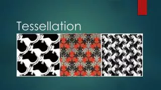
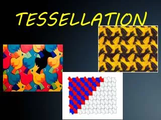
Patches / Control Points • Model geometry for tessellation uses patches and control points • A patch is a line, triangle or quad, which is bent or shaped by some number of control points • For example, a Bezier spline • DirectX does not specify the available patch types • We can choose any and implement it in hull and domain shaders • This is potentially a huge change for game asset creation • Patches suit artwork creation much better than polygonal modelling A quad patch and control points Head made from quad patches
Hull Shader • The hull shader gets access to all the control points for a single patch and can process them in any way • It outputs the final control points used to shape the patch • It can output greater or fewer control points if necessary • For many tessellation purposes, we don’t need to change the control points given • Often the vertex shader converts to world space & they’re ready • So many hull shaders just copy input to output • However, they can be used for advanced purposes: • Approximating complex input splines using simpler output splines • Providing per-control-point information to help the patch constant function (see next slide)
Patch Constant Function • The patch constant function is called once per patch • It must decide how much to tessellate each patch • It can also output other custom per-patch data • It can access the input control points and the hull shader ouput control points (as arrays) to do its job • Patch tessellation is specified as one Interior Tessellation Factor and three or four Edge Tessellation Factors • That is for a triangle or quad patch. A line only has one factor • These factors specify how much to divide the edges and split up the interior of each patch (see next slides) • A simple patch constant function can just set fixed values • More commonly the factors are increased as models get nearer, or for more complex areas of the geometry
Tessellation Stage • The tessellation stage uses the factors specified in the patch constant function • Divides up a unit square, triangle or line based on the factors • It works in a generic 0->1 space • Usually referred to with UV axes • Outputs this generic geometry as vertices for the domain shader next • Several fixed algorithms are available for the tessellation • Specify in the hull shader code Edge Factors 3,1,1,1Interior Factors: 1,1(Horizontal / Vertical) Edge Factors 1,1,1,1Interior Factors: 4,4 Edge Factors 4,4,4,4Interior Factors: 4,4
Domain Shader • The domain shader: • Takes control points output from the hull shader • And the generic vertices output from the tessellation stage • Combine to create final tessellation for the scene • Exactly what this involves depends on the patch type • At least involves transforming generic vertices to world space • Then some manipulation based on the control points Five Control points shaping a tessellated quad Number of control points and formula used for shaping decided by programmer, e.g. NURBs Catmull-Clark surfaces, etc.
Distance / Density Variation • It is common to vary the amount of tessellation used based on the geometry distance or complexity (density) • Distance variation is simpler: • The patch control function can look at the distance of the control points to the camera • Make tessellation factor decisions based on that • Density variation needs pre-processing: • The patch control function can get an integer ID for each patch • So analyse the complexity of each patch offline • Store complexity in an array (1D texture) indexed by patch ID • Patch control function reads this array to choose tessellation factors
“Water-tight” Patch Seams • As soon as we vary tessellation per-patch, there are problems with patch seams • Cracks in the geometry appearing at the edges between patches of different tessellation • That is why we can control the edge tessellation separately • Ensure all edges have the same tessellation factor in the patch on each side (watertight seams) • Additional processing for the patch constant function / hull shader Adjacent patches, different tessellation – causes crack at seam Match edge tessellation to create “watertight” seams
Displacement Mapping • Displacement mapping is adjusting the height of vertices based on heights stored in a texture (a height map) • Effectively, this is parallax mapping done properly • Result has correct silhouettes and no visual problems • Requires finely detailed geometry, so it works well with tessellation • A very effective method to provide fine geometry detail with less expense – and to make most effective use of the tessellation • Can be used on most kinds of patch Parallax Mapping Tessellation + Height Map Displacement Mapping
Displacement Mapping • Control points and patches seem far from a game’s polygonal models • But, can use displacement mapping and tessellation on polygons too: • Call each triangle a patch • Call the three vertices control points • Use tessellation to create interior vertices and triangles • Hull shader just copies control points • Domain shader transforms generic tessellated triangle to position of original triangle – tangent-space work for this • Displacement mapping on result vertices • Need height map for displacement and a normal map for lighting • Same requirements as parallax mapping Triangle TessellationUsed on polygonal mesh
Technical Issues • Tessellation has performance implications: • A very efficient method to draw large number of polygons • However, minimise it: don’t tessellate off-screen, use lower tessellation in the distance, fall back to normal mapping etc. • Displacement mapping brings more seam issues: • Any discontinuity in texture, e.g. where two different textures meet, will cause a discontinuity in displacement (i.e. cracks) • Even with the most careful mapping, this cannot be avoided • Solve by specifying a dominant texture at patch seams • Extra coding in the hull shader / patch constant function • Sharp edges cause cracks (use normal map or averaging at edges) • Models must be designed with displacement in mind • Very low polygon models won’t work well. Start with the basic shape of the height map designed into the geometry (see lab)
Future for Tessellation in Games • Will see tessellation / displacement mapping on standard polygonal models in the lab • However, these technologies allow us to start using patch / control point based geometry instead • Artists have long used patch-basedmodelling for commercial animation • Catmull-Clark subdivision surfacesare quite well suited to GPU tessellation • A low polygon surface that mathematically defines a curved patch • There have been a few experiments with these in games already, expect to see variants of these used more frequently