Download
1 / 53
541 likes | 801 Views
Ch.2 – Networking Fundamentals. CCNA 1 version 3.0. Overview. Students completing this module should be able to: Explain the importance of bandwidth in networking. Use an analogy from their experience to explain bandwidth. Identify bps, kbps, Mbps, and Gbps as units of bandwidth.

E N D
Ch.2 – Networking Fundamentals CCNA 1 version 3.0
Overview Students completing this module should be able to: • Explain the importance of bandwidth in networking. • Use an analogy from their experience to explain bandwidth. • Identify bps, kbps, Mbps, and Gbps as units of bandwidth. • Explain the difference between bandwidth and throughput. • Calculate data transfer rates. • Explain why layered models are used to describe data communication. • Explain the development of the Open System Interconnection model (OSI). • List the advantages of a layered approach. • Identify each of the seven layers of the OSI model. • Identify the four layers of the TCP/IP model. • Describe the similarities and differences between the two models. • Briefly outline the history of networking. • Identify devices used in networking. • Understand the role of protocols in networking. • Define LAN, WAN, MAN, and SAN. • Explain VPNs and their advantages. • Describe the differences between intranets and extranets
Data networks • One early solution was the creation of local-area network (LAN) standards. Because LAN standards provided an open set of guidelines for creating network hardware and software, the equipment from different companies could then become compatible. • This allowed for stability in LAN implementation. • In a LAN system, each department of the company is a kind of electronic island. • As the use of computers in businesses grew, it soon became obvious that even LANs were not sufficient.
Data networks • What was needed was a way for information to move efficiently and quickly, not only within a company, but also from one business to another. • The solution was the creation of metropolitan-area networks (MANs) and wide-area networks (WANs).
Network topology • Network topology defines the structure of the network. • Physical topology, which is the actual layout of the wire or media. • Logical topology, which defines how the media is accessed by the hosts for sending data. • The logical topology of a network is how the hosts communicate across the medium. • The two most common types of logical topologies are broadcast and token passing.
Bus Topology “A bus topology uses a single backbone segment (length of cable) that all the hosts connect to directly.”
Ring Topology “A ring topology connects one host to the next and the last host to the first. This creates a physical ring of cable.”
Token Ring • Token Ring NIC and Hub (or MAU)
Star Topology “A star topology connects all cables to a central point of concentration. This point is usually a hub or switch, which will be described later in the chapter.”
Extended Star Topology “An extended star topology uses the star topology to be created. It links individual stars together by linking the hubs/switches. This, as you will learn later in the chapter, will extend the length and size of the network.”
Hierarchical Topology Only one definition -> “A hierarchical topology is created similar to an extended star but instead of linking the hubs/switches together, the system is linked to a computer that controls the traffic on the topology.”
Hierarchical Topology Another definition -> A hierarchical design or model is one that implements a layered approach to networking. This is discussed later in CCNP courses.
Mesh Topology “A mesh topology is used when there can be absolutely no break in communications, for example the control systems of a nuclear power plant. So as you can see in the graphic, each host has its own connections to all other hosts. This also reflects the design of the Internet, which has multiple paths to any one location.” There are also full mesh and partial mesh topologies, both physical and logical, which will be discussed later in CCNA semester 4.
Network protocols • Protocol suites are collections of protocols that enable network communication from one host through the network to another host. • A protocol is a formal description of a set of rules and conventions that govern a particular aspect of how devices on a network communicate. Protocols determine the format, timing, sequencing, and error control in data communication. • Without protocols, the computer cannot make or rebuild the stream of incoming bits from another computer into the original format.
Network protocols Protocols control all aspects of data communication, which include the following: • How the physical network is built • How computers connect to the network • How the data is formatted for transmission • How that data is sent • How to deal with errors Examples • Institute of Electrical and Electronic Engineers (IEEE), • American National Standards Institute (ANSI), • Telecommunications Industry Association (TIA), • Electronic Industries Alliance (EIA) • International Telecommunications Union (ITU), formerly known as the Comité Consultatif International Téléphonique et Télégraphique (CCITT).
Local-area networks (LANs) Some common LAN technologies are: • Ethernet • Token Ring • FDDI
Wide-area networks (WANs) Some common WAN technologies are: • Modems • Integrated Services Digital Network (ISDN) • Digital Subscriber Line (DSL) • Frame Relay • US (T) and Europe (E) Carrier Series – T1, E1, T3, E3 • Synchronous Optical Network (SONET)
Metropolitan-area networks (MANs) • A MAN is a network that spans a metropolitan area such as a city or suburban area. • A MAN usually consists of two or more LANs in a common geographic area. • For example, a bank with multiple branches may utilize a MAN.
Storage-area networks (SANs) • A SAN is a dedicated, high-performance network used to move data between servers and storage resources. • SANs offer the following features: • Performance – SANs enable concurrent access of disk or tape arrays by two or more servers at high speeds, providing enhanced system performance. • Availability – SANs have disaster tolerance built in, because data can be mirrored using a SAN up to 10 kilometers (km) or 6.2 miles away. • Scalability – Like a LAN/WAN, it can use a variety of technologies. This allows easy relocation of backup data, operations, file migration, and data replication between systems.
Virtual private network (VPN) • VPN is a private network that is constructed within a public network infrastructure such as the global Internet. • Using VPN, a telecommuter can access the network of the company headquarters through the Internet by building a secure tunnel between the telecommuter’s PC and a VPN router in the headquarters. • A VPN is a service that offers secure, reliable connectivity over a shared public network infrastructure such as the Internet.
Benefits of VPNs The following are the three main types of VPNs: • Access VPNs – Access VPNs provide remote access to a mobile worker and small office/home office (SOHO) to the headquarters of the Intranet or Extranet over a shared infrastructure. • Intranet VPNs – Intranet VPNs link regional and remote offices to the headquarters of the internal network over a shared infrastructure using dedicated connections. Allow access only to the employees of the enterprise. • Extranet VPNs – Extranet VPNs link business partners to the headquarters of the network over a shared infrastructure using dedicated connections. Allow access to users outside the enterprise.
Intranets and extranets • Intranets are designed to permit access by users who have access privileges to the internal LAN of the organization. • Within an Intranet, Web servers are installed in the network. • Browser technology is used as the common front end to access information such as financial data or graphical, text-based data stored on those servers. • Extranets refer to applications and services that are Intranet based, and use extended, secure access to external users or enterprises. • This access is usually accomplished through passwords, user IDs, and other application-level security.
Importance of bandwidth • Bandwidth is defined as the amount of information that can flow through a network connection in a given period of time. • Available at http://www.thinkgeek.com
Measurement • In digital systems, the basic unit of bandwidth is bits per second (bps). • Bandwidth is the measure of how much information, or bits, can flow from one place to another in a given amount of time, or seconds.
Limitations • Bandwidth varies depending upon the type of media as well as the LAN and WAN technologies used. • The physics of the media account for some of the difference. • Signals travel through twisted-pair copper wire, coaxial cable, optical fiber, and air. • The actual bandwidth of a network is determined by a combination of the physical media and the technologies chosen for signaling and detecting network signals.
Throughput • Throughput refers to actual measured bandwidth, at a specific time of day, using specific Internet routes, and while a specific set of data is transmitted on the network. • Throughput is often far less than the maximum possible digital bandwidth of the medium that is being used. Internetworking devices The following are some of the factors that determine throughput: • Type of data being transferred • Network topology • Number of users on the network • User computer • Server computer • Power conditions
Data transfer calculation • Using the formula transfer time = size of file / bandwidth (T=S/BW) allows a network administrator to estimate several of the important components of network performance. • If the typical file size for a given application is known, dividing the file size by the network bandwidth yields an estimate of the fastest time that the file can be transferred.
Digital versus analog • Analog bandwidth is measured by how much of the electromagnetic spectrum is occupied by each signal. • The basic unit of analog bandwidth is hertz (Hz), or cycles per second. • While analog signals are capable of carrying a variety of information, they have some significant disadvantages in comparison to digital transmissions. • The analog video signal that requires a wide frequency range for transmission cannot be squeezed into a smaller band. • Therefore, if the necessary analog bandwidth is not available, the signal cannot be sent. • In digital signaling all information is sent as bits, regardless of the kind of information it is. This is discussed in later chapters in more detail.
Other information • For most of this chapter we will rely on other sources. • Comer does a good job in explaining “what happens” but does not provide enough information to see “how it works.” • Sources used for this presentation:
Digital and Analog Bandwidth Bandwidth = The width or carrying capacity of a communications circuit. Digital bandwidth = the number of bits per second (bps) the circuit can carry • used in digital communications such as T-1 or DDS • measure in bps • T-1 -> 1.544 Mbps Analog bandwidth = the range of frequencies the circuit can carry • used in analog communications such as voice (telephones) • measured in Hertz (Hz), cycles per second • voice-grade telephone lines have a 3,100 Hz bandwidth
Digital and Analog Bandwidth Digital Signals • digital signal = a signal whose state consists of discrete elements such as high or low, on or off Analog Signals • analog signal = a signal which is “analogous” to sound waves • telephone lines are designed to carry analog signals
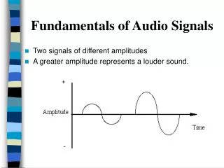
Analog Signals, Modulation and Modem Standards • A perfect or steady tone makes a wave with consistent height (amplitude) and pitch (frequency) which looks like a sine wave. (Figure 4-15) • A cycle or one complete cycle of the wave • The frequency (the number of cycles) of the wave is measured in Hertz • Hertz (Hz) = the number of cycles per second
Using layers to analyze problems in a flow of materials • The concept of layers is used to describe communication from one computer to another. • The OSI and TCP/IP models have layers that explain how data is communicated from one computer to another. • The models differ in the number and function of the layers. • However, each model can be used to help describe and provide details about the flow of information from a source to a destination.
Using layers to describe data communication • In order for data packets to travel from a source to a destination on a network, it is important that all the devices on the network speak the same language or protocol. • A protocol is a set of rules that make communication on a network more efficient.
OSI model • To address the problem of network incompatibility, the International Organization for Standardization (ISO) researched networking models like Digital Equipment Corporation net (DECnet), Systems Network Architecture (SNA), and TCP/IP in order to find a generally applicable set of rules for all networks. • Using this research, the ISO created a network model that helps vendors create networks that are compatible with other networks. • The Open System Interconnection (OSI) reference model released in 1984 was the descriptive network model that the ISO created. • It provided vendors with a set of standards that ensured greater compatibility and interoperability among various network technologies produced by companies around the world.
OSI layers • It breaks network communication into smaller, more manageable parts. • It standardizes network components to allow multiple vendor development and support. • It allows different types of network hardware and software to communicate with each other. • It prevents changes in one layer from affecting other layers. • It divides network communication into smaller parts to make learning it easier to understand.
Peer-to-peer communications • In order for data to travel from the source to the destination, each layer of the OSI model at the source must communicate with its peer layer at the destination. • This form of communication is referred to as peer-to-peer. • During this process, the protocols of each layer exchange information, called protocol data units (PDUs). • Each layer of communication on the source computer communicates with a layer-specific PDU, and with its peer layer on the destination computer as illustrated in Figure
TCP/IP model • Unlike the proprietary networking technologies mentioned earlier, TCP/IP was developed as an open standard. • This meant that anyone was free to use TCP/IP. This helped speed up the development of TCP/IP as a standard. • Although some of the layers in the TCP/IP model have the same name as layers in the OSI model, the layers of the two models do not correspond exactly.
TCP/IP model Some of the common protocols specified by the TCP/IP reference model layers. Some of the most commonly used application layer protocols include the following: • File Transfer Protocol (FTP) • Hypertext Transfer Protocol (HTTP) • Simple Mail Transfer Protocol (SMTP) • Domain Name System (DNS) • Trivial File Transfer Protocol (TFTP) The common transport layer protocols include: • Transport Control Protocol (TCP) • User Datagram Protocol (UDP) The primary protocol of the Internet layer is: • Internet Protocol (IP)
TCP/IP model Networking professionals differ in their opinions on which model to use. Due to the nature of the industry it is necessary to become familiar with both. Both the OSI and TCP/IP models will be referred to throughout the curriculum. The focus will be on the following: • TCP as an OSI Layer 4 protocol • IP as an OSI Layer 3 protocol • Ethernet as a Layer 2 and Layer 1 technology Remember that there is a difference between a model and an actual protocol that is used in networking. The OSI model will be used to describe TCP/IP protocols.
Detailed encapsulation process • All communications on a network originate at a source, and are sent to a destination. • The information sent on a network is referred to as data or data packets. If one computer (host A) wants to send data to another computer (host B), the data must first be packaged through a process called encapsulation.