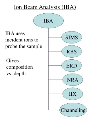
Ion Beam Analysis (IBA)
700 likes | 987 Views
Explore the principles and applications of Ion Beam Analysis (IBA) methods including SIMS, RBS, ERD, NRA. Learn about interactions of ions with matter and energy loss mechanisms. Discover how these techniques provide valuable depth and composition information.

Ion Beam Analysis (IBA)
E N D
Presentation Transcript
Ion Beam Analysis (IBA) IBA IBA uses incident ions to probe the sample SIMS RBS Gives composition vs. depth ERD NRA IIX Channeling
IBA • 2 ways in which ions interact with matter and lose energy Elastic Collisions Inelastic Collisions • Coulomb interaction • between ion and • nuclear cores • (Rutherford scattering) • Produces recoil atoms • Ion interacts with atomic electrons in solid and loses energy
IBA • Elastic collisions : • Interaction between ion and nuclear core (Rutherford scattering) • Described as binary collision Before collision M0, E0 Mr After collision Mr, Er q f M0, Es
IBA • Incident ion transfers kinetic energy to recoiling particle • Conservation of energy and momentum : • Er = 4 E0 MoMrcos2q/(M0+Mr)2 • Can measure energy of recoiling particle (principle of SIMS & ERD) After collision Mr, Er M0, E0 q M0, Es f
IBA • Incident ion loses energy as it propagates through sample • Conservation of energy and momentum (for elastic collisions): 2 Es = E0 (Mr2 – M02sin2f)½ + M0cosf M0 + Mr • Can measure energy of scattered incident ion (principle of RBS) After collision Mr, Er M0, E0 q M0, Es f
IBA • Inelastic collisions : • Due to interaction of ions with electrons Total rate of energy loss: dE/dx = - N [ Se(E) + Sn(E) ] target atom density [cm-3] stopping power [eV/Å] nuclear stopping cross-section [eV cm2] electronic stopping cross-section [eV cm2] • e.g., for 1 keV Ar+ ions in Al • dE/dx = 39 eV/Å
IBA dE/dx nuclear elastic scattering electronic inelastic scattering E ~ MeV’s ~ 1 keV RBS ERD IIX NRA SIMS • Detection of scattered ions (incident or recoil) and their energies gives information on sample
SIMS • Secondary ion mass spectrometry • Incident ion beam • 1 – 20 keV • Ar+, Cs+, O+ • Sputtered atoms are sorted by mass (mass analyzed) • Sputtered surface recedes • Gives composition versus depth mass analyzer incident ion (e.g., Ar+) sputtered atoms sample
SIMS • Static SIMS vs Dynamic SIMS • Compositional mapping achieved by scanning incident ion beam across the sample surface • Lateral resolution ~ 100 mm from Feldman and Mayer, Fig. 4.7, p. 81
SIMS • Applications : • Determine presence and location (depth and lateral position) of impurities or dopants (dopant profiling) • Measures the dopant profile not the carrier density From LaPierre, Ph.D. thesis O C 2H
SIMS • Depth calibration • Measure ion current • Use calibration layers • Measure etch pit depth (e.g., stylus profilometry) • Errors • At large depths (long sputtering times) bottom of crater can become rough • Sputtering of crater walls • Ion-induced mixing/implantation
SIMS • Depth resolution • ~ 5 – 10 Å = depth from which sputtered atoms are emitted from Stradling and Klipstein, Fig. 2, p. 89
SIMS Quantification Y = # sputtered (ejected) target atoms # incident ions [Y] = atoms/ion Typical sputtering yields are between 0.1 and 4 From Ohring, Table 3-4, p. 113
SIMS Quantification • In SIMS, charged ions are detected and mass analyzed • Y+ = secondary ion yield = # sputtered ions # sputtered atoms [Y+] = ions/atom
SIMS Quantification Y+ ~ 10-4 - 1 from Feldman and Mayer, Fig. 4.13(a), p. 86
SIMS Quantification • A general theory to explain Y+ does not exist • Y+ depends on many factors • Surface conditions (e.g., oxidation) • Ion species being sputtered • Sputtered ion energy • Sample composition • Positive ion yield frequently enhanced when using O2- beams • Negative ion yield frequently enhanced when using Cs+ beams
SIMS Quantification • Comparison with known sample required for absolute quantitative analysis • But, SIMS is highly sensitive, ~ 1016 cm-3
RBS • Rutherford Backscattering Spectrometry • Light, 1-3 MeV ions (e.g., 4He) backscatter from target atoms (Rutherford scattering) • Measure energy of backscattered ions • Gives composition versus depth Transmitted beam from Chu et al, Fig. 2.4, p. 28
RBS from Chu et al, Fig. 6.1, p. 154 • Ions detected by solid state (Si) detector, similar to EDX detector
RBS From Ohring, Fig. 6-23, p. 293
RBS • Elastic collisions : • Interaction between ion and nuclear core (Rutherford scattering) • Described as binary collision Before collision M0, E0 M2 Mr After collision M0, E0 Mr, Er q M0, Es f
RBS K = kinematic factor = Es/E0 = (Mr2 – M02sin2f)½ + M0cosf 2 M0 + Mr • Incident ion: M0, E0 known • Detection angle fixed: f known • K measured for backscattered ion • Can determine Mr (atomic components of sample) After collision M0, E0 Mr, Er q M0, Es f
RBS • Example: impurities on a surface Eo Carbon Substrate Es1 (Au) Es2 (Si) Es3 (O) Es4 (C) from Chu et al, Fig. 5.1, p. 124
RBS • K increases with M2→ peak position identifies element from Feldman and Mayer, Fig. 2.2, p. 16 from Chu et al, Fig. 5.1, p. 124
RBS • Ions scattered throughout depth of film • Ions lose energy during transit in film primarily due to inelastic electron scattering After collision Mr, Er M0, E0 q M0, Es f M0, Es - DE
RBS From Ohring, Fig. 6-21, p. 290
RBS Typical RBS spectrum From Ohring, Fig. 6-21, p. 290
RBS From Ohring, Fig. 6-24, p. 295
RBS • Energy of leading edge gives element identification From Ohring, Fig. 6-21, p. 290
RBS • Width of peak related to film thickness • Can convert energy scale to depth scale From Ohring, Fig. 6-21, p. 290
RBS Depth Scale From Ohring From Ohring, Fig. 6-21, p. 290 • Ions lose energy at the rate dE/dx (stopping power) • Incident path, x = - ∫ dE / (dE/dx) • Outgoing path, x = - ∫ dE / (dE/dx) E2 E1 E4 E3 • Stopping power, dE/dx, varies with energy, E
RBS Depth Scale • dE/dx varies with energy dE/dx nuclear elastic scattering electronic inelastic scattering E ~ keV’s ~ MeV’s
RBS Depth Scale • Approximation (valid for thin films) : • (dE/dx)incident path ~ dE/dx at E1 • (dE/dx)outgoing path ~ dE/dx at E4 From Ohring, Fig. 6-21, p. 290
RBS Depth Scale • Incident path: • x = - ∫ dE / (dE/dx)E1 • = - (E2 – E1) / (dE/dx)E1 • Outgoing path: • x = - ∫ dE / (dE/dx)E4 • = - (E4 – E3) / (dE/dx)E4 • = - (E4 – KE2) / (dE/dx)E4 • Can eliminate E2 and solve for x E2 E1 E4 E3
RBS Depth Scale • x = (KE1 – E4) / [ K (dE/dx)E1 + (dE/dx)E4 ] • E1 , (dE/dx)E1, (dE/dx)E4 are known • Measure E1, E4 • Can determine x • Depth resolution ~ 10-20 nm (determined by energy resolution of MCA ~ few keV) From Ohring, Fig. 6-21, p. 290
RBS • Height of peak gives amount of element present From Ohring, Fig. 6-21, p. 290
RBS Quantification • The number of backscattered ions gives the composition • # scattered particles : • Y = Q (Nt) (ds/dW) W detector solid angle total # of incident ions # atoms per unit area Differential scattering cross-section = scattering cross-section per unit solid angle, W • ds/dW given by famous Rutherford scattering formula : • ds/dW~ (Z1Z2e2 / 4Eo)2 sin-4(f/2)
RBS Quantification • Example: impurities on a surface • Peak position identifies element • Peak height identifies amount of element Eo Carbon Substrate Es1 (Au) Es2 (Si) Es3 (O) Es4 (C) from Chu et al, Fig. 5.1, p. 124
RBS Quantification • Quantification • Method 1: Theoretical • Amount of impurity per unit area = • (Nt)i = Yi / [ Q(ds/dW)iW] • If geometry (W, f) is well known from Chu et al, Fig. 5.1, p. 124
RBS Quantification • Quantification • Method 2: Comparison with substrate peak • Substrate: • Ys = Q {Ns [dE/(dE/dx)s]} (ds/dW)sW depth, x, corresponding to dE One energy channel ~ few keV Ys from Chu et al, Fig. 5.1, p. 124
RBS Quantification • Quantification • Method 2: Comparison with substrate • Impurity Atom: • Yi = Q (Ni t) (ds/dW)sW Ys from Chu et al, Fig. 5.1, p. 124
RBS Quantification • Quantification • Method 2: Comparison with substrate • Ratio: • Yi / Ys = (dsi/dW)i (Nt)i • (dss/dW)s Ns dE/(dE/dx)s • ds/dW ~ Z2 • Yi / Ys = Zi2 (Nt)i • Zs2 NsdE / (dE/dx)s • (Nt)i = (Yi/Ys) (Zs/Zi)2 [Ns dE / (dE/dx)s]
RBS Quantification • Sensitivity • ~ 1012 – 1014 cm-2 • ~ 1 at % • Lateral resolution ~ mm to mm • MCA detects energy difference of a few keV → determines region of good mass resolution from Feldman and Mayer, Fig. 2.2, p. 16
RBS • Major advantage of RBS • Quantitative capability • Problem with RBS : • Difficult to detect light elements in a heavy mass substrate • Overlap produces small signal on large background • Problem solved by using ERD adapted from Chu et al., Fig. 8.21, p. 248
ERD • Elastic Recoil Detection : • Use light MeV ions at glancing incidence; e.g., 4He • Detect energy of recoiling atoms • Gives composition versus depth • Useful for light element detection in sample (e.g., H, D) Mr, Er q After collision f M0, Es M0, E0
ERD • Elastic Recoil Detection : • Al foil blocks backscattered (incident) ions (M0, E0); ds/dW ~ Z2 • Lighter recoil atoms (M2, E2) pass to detector detector Al foil Mr, Er q After collision f M0, Es M0, E0
ERD • = Er/E0 = [ 4M0Mr / (M0 + Mr)2 ] cos2q • Incident ion: M0, E0 known • Detection angle fixed: q known • g measured for backscattered ion • Can determine Mr (atomic components of sample) versus depth Mr, Er q After collision f M0, Es M0, E0
IIX • Ion Beam Induced X-ray Emission : • Light MeV ion causes inner shell ionization • Outer shell electron fills vacancy • Measure energy of characteristic x-ray emission → Identify atomic species • Similar to EDX After collision M0, E0 Mr M0, Es
IIX • Typical IIX Spectrum from Mayer and Rimini, Fig. 5.1, p. 315
IIX Quantification • Can determine amount of element present by measuring x-ray line intensity (same as EDX) • Solid state (Si) detector • Intensity of x-rays from a depth d is : • I = Q(d)cswx e-md/cosq e dW/4p • Q(d) = intensity of ion-beam at depth d • c = atomic concentration • s = ionization cross-section • wx = x-ray yield (fluorescence yield) • m = x-ray absorption coefficient • e = detector efficiency • dW = detector solid angle • q = detector angle wrt ion-beam