Download
1 / 14
140 likes | 289 Views
Example 3.1 Air flows from a reservoir where P = 300 kPa and T = 500 K through a throat to section 1 in Fig. 3.4, where there is a normal – shock wave. Compute (a) P 1 (b) P 2 (c) P o2 (d) A* 2 (e) P o3 (f) A* 3 1 2 3

E N D
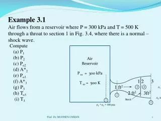
Example 3.1Air flows from a reservoir where P = 300 kPa and T = 500 K through a throat to section 1 in Fig. 3.4, where there is a normal – shock wave. Compute (a) P1 (b) P2 (c) Po2 (d) A*2 (e) Po3 (f) A*31 2 3 (g) P3 1 ft2 (h) To3 2 ft2 3ft2 (i) T3 Air Reservoir P o1 = 300 kPa T o1 = 500 K Prof. Dr. MOHSEN OSMAN
A shock wave cannot exist unless M1 is supersonic; therefore the flow must have accelerated through a throat which is sonicWe can now find the Mach no. M1 from the known isentropic area ratioFrom isentropic Table at we get M1 = 2.20The pressure P1 follows from the isentropic table The pressure P2 is now obtained from M1 and the normal-shock Table In similar manner, for M1 = 2.2, from Normal Shock Table Then & Prof. Dr. MOHSEN OSMAN
The flow from section 2 to 3 is isentropic ( but at higher entropy than the flow upstream of the shock)Knowing , we can now compute by finding and withoutbothering to find ( which is equal to 0.547 ).The area ratio at section 3 is Then, since is known to be subsonic because it is downstream of a normal shock, from isentropic Table, we get The pressure then follows from Meanwhile, the flow is adiabatic throughout the duct; thus Prof. Dr. MOHSEN OSMAN
Example # 3.2 An explosion in air, creates a spherical shock wave propagat- ingradially into still air at standard conditions. At the instant shown in figure the pressure just inside the shock is 200 psia. Estimate (a) The shock speed C & (b) the air velocity V just inside the shock atmospheric conditions Speed of sound P = 14.7 psia In U.K. units T = 520 R in Rankine Prof. Dr. MOHSEN OSMAN
Solution (a) In spite of the spherical geometry the flow across the shock waves normal to the spherical wave front; hence the normal- shock relations (3.2) to (3.11) apply. Fixing our control volume to the moving shock, we find that the proper conditions to use in Fig. 3.1 are : The speed of sound outside the shock is We can find from the known pressure ratio across the shock From Normal-Shock Table, we get Prof. Dr. MOHSEN OSMAN
(b) To find , we need the temperature or sound speed inside the shock. Since is known, from Normal-Shock Table for M1 = 3.436, we get T2 = 3.228(520) = 1679 RAt such a high temperature we should account for non-perfect- gas energy equation that:Notice that we did that without bothering to compute M2 , which equals 0.454, or Finally, the air velocity behind the shock is Thus a powerful explosion creates a brief but intense blast wind as it passes. Prof. Dr. MOHSEN OSMAN
Operation of Converging and Diverging Nozzles By combining the isentropic flow and normal-shock relations plus the concept of sonic throat chocking, we can outline the characteristics of converging and diverging nozzles. Converging Nozzle Fig. 3.6 Operation of a Converging Nozzle (a) Nozzle geometry showing characteristic pressures; (b) Pressure distribution caused by various back pressures; (C) Mass flux versus back pressure. Prof. Dr. MOHSEN OSMAN
Converging Nozzle First consider the converging nozzle sketched in 3.6 a. There is an upstream reservoir at stagnation pressure Po . The flow is induced by lowering the downstream outside, or back, pressure Pb , resulting in the sequence of states a to e shown in Fig. 3.6 b and c. For a moderate drop in Pb to states a and b, the throat pressure is higher than the critical value P* which would make the throat sonic. The flow in the nozzle is subsonic throughout, and the jet exit pressure Pe equals the back pressure Pb. The mass flux is predicted by subsonic isentropic theory and is less than the critical value as shown in Fig. 3.6 c. For condition ( c ), the back pressure exactly equals the critical pressure P* of the throat. The throat becomes sonic, the jet exit flow is sonic, Prof. Dr. MOHSEN OSMAN
Pe = Pb, and the mass flux equals its maximum valuefromThe flow upstream of the throat is subsonic everywhere and predicted by isentropic theory based on the local area ratio and Isentropic Table. Prof. Dr. MOHSEN OSMAN
Finally, if Pb is lowered further to conditions (d) or (e) below P* the nozzle cannot respond further because it is chocked at its maximum throat mass flux. The throat remains sonic with Pe = P*, and the nozzle pressure distribution is the same as in state c , as sketched in Fig. 3.6 b. The exit jet expands supersonically so that the jet pressure can be reduced from P* down to Pb. The jet structure is complex and multi-dimensional and not shown here. Being supersonic, the jet cannot send any signal upstream to influence the chocked flow conditions in the nozzle. Prof. Dr. MOHSEN OSMAN
Operation of Converging and Diverging NozzleConverging – Diverging Nozzle Figure 3.7 Flow through converging-diverging nozzle under variable back pressure. Prof. Dr. MOHSEN OSMAN
Now consider the converging-diverging nozzle sketched in Fig. 3.7a. If the back pressure Pb is low enough, there will be supersonic flow in the diverging portion and a variety of shock-wave conditions may occur, which are sketched on Fig. 3.7b. Let the back pressure be gradually decreased. For curves A and B in Fig. 3.7b, the back pressure is not low enough to induce sonic flow in the throat, and the flow in the nozzle is subsonic throughout. The pressure distribution is computed from subsonic isentropic area-change relations, e.g., Isentropic Table. For curve C the area ratio exactly equals for a subsonic Me in isentropic Table. The throat becomes sonic, and mass flux reaches a maximum in Fig. 3.7c. Prof. Dr. MOHSEN OSMAN
The remainder of the nozzle flow is subsonic, including the exit jet, and Pe = Pb .Now jump for a moment to curve H. Here Pb is such that exactly corresponds to the critical area ratio for a supersonic Me in the table. The diverging flow is entirely supersonic, including the jet flow, and Pe = Pb . This is called the design pressure ratio of the nozzle and is the back pressure suitable for operating a supersonic wind tunnel or an efficient rocket nozzle.Now back up and suppose that Pblies between curves C and H, which is impossible according to purely isentropic flow calculations. Then back pressure D to F occur in Fig. 3.7b. The throat remains chocked at the sonic value, and Prof. Dr. MOHSEN OSMAN
we can match Pe = Pb by placing a normal shock at just the right place in the diverging section to cause a subsonic diffuser flow back to the back-pressure condition.The mass flux remains at maximum in Fig. 3.7c. At back pressure F, the required normal shock stands in the duct exit . At back pressure G no single normal shock can do the job, and so the flow compresses outside the exit in a complex series of oblique shocks until it matches Pb.Finally, at back pressure I, Pb is lower than the design pressure H but the nozzle is chocked and cannot respond. The exit flow expands in a complex series of supersonic wave motion until it matches the low back pressure. Prof. Dr. MOHSEN OSMAN