Download
1 / 18
180 likes | 203 Views
Understand electric fields, Gauss' Law, Faraday's Law, RC/RL circuits, and AC circuits. Learn about charges, conductors, potential energy, and Gauss' law applications. Explore the concepts through examples and calculations.

E N D
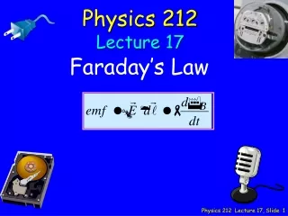
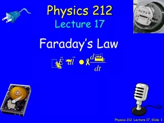
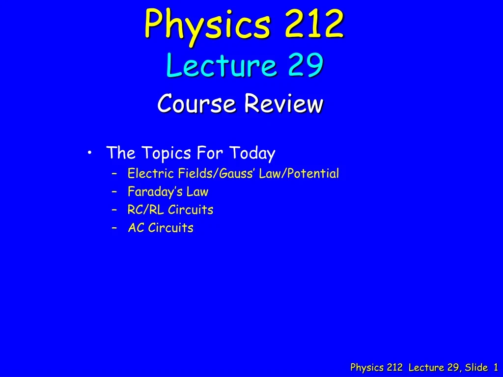
Physics 212 Lecture 29 Course Review • The Topics For Today • Electric Fields/Gauss’ Law/Potential • Faraday’s Law • RC/RL Circuits • AC Circuits
Music “Rediscovered” Soul singer from 60’s Absolutely Beautiful Voice Why? Great singer to end the course Highly Recommended DVD: “One Night History of the Blues” • Who is the Artist? • Ray Charles • Solomon Burke • Henry Butler • Johnny Adams • Otis Redding Physics 212 Lecture 29
Electric Field Horizontal components cancel E from top arc points down E from bottom arc points up Etotal points down Calculation: q sinq q q Two curved rods each have charge +Q uniformly distributed over their lengthWhich statement best describes the electric field due to these two rods at the midpointbetween the two rods (marked by an X) A. E points up B. E points down C. E = 0 48% Top arc produces smaller horizontal components
Conductors, Potential Energy E = 0 inside shell Spherical symmetry & Gauss’ law No work done to move q E = 0 inside shell No change in potential energy ! A thin non-conducting spherical shell carries a positive charge Q spread uniformlyover the surface of the shell. A positive test charge q is located inside the shell. Compare UA, the potential energy of the test charge in position A (near the shell)with UB, the potential energy of the test charge in position B (center of the shell) A. UA > UBB. UA = UBC. UA < UB 53% Potential Energy is a measure of work done by E field
Electric Potential, Gauss’ Law ALWAYS START FROM DEFINITION OF POTENTIAL (D) (A) Spherical symmetry & Gauss’ law determines E (B) a < r < b: (E) (C) A thin non-conducting spherical shell of radius a carries a uniformly distributed net surface charge 2Q. A second thin non-conducting shell of radius b carries a uniformly distributed net surface charge 3Q. The two shells are concentric. Calculate the potential difference DV = V(a) – V(b) between the inner and outershells. 37%
Electric Potential, Gauss’ Law (D) (A) (B) Spherical symmetry & Gauss’ law determines E (E) r < a: (C) A thin non-conducting spherical shell of radius a carries a uniformly distributed net surface charge 2Q. A second thin non-conducting shell of radius b carries a uniformly distributed net surface charge 3Q. The two shells are concentric. Calculate the potential difference DV = V(a) – V(0) between the inner shell and the origin. 45%
Gauss’ Law, Conductors Spherical symmetry & Gauss’ law determines E A solid conducting sphere of radius a is centered on the origin, and carries a total charge Q1. Concentric with this sphere is a conducting spherical shell of inner radius b and outer radius c, which carries a total charge Q2. What is the surface charge density, sb, on the inner surface of the outer spherical shell (r = b)? 59% (D) (A) (C) (B) (E) Charge must be induced to insure E = 0 within conducting shell Physics 212 Lecture 29, Slide 7
Gauss’ Law Eliminate (a) and (c) a < r < b: E = kQ1/r2 r > c: E = k(Q1+Q2)/r2 Q1 = -3mC Q1 + Q2 = +2mC For r > c, E must be less than the continuation of E from a to b Q1 = - 3 mCQ2 = 5 mC A solid conducting sphere of radius a is centered on the origin, and carries a total charge Q1. Concentric with this sphere is a conducting spherical shell of inner radius b and outer radius c, which carries a total charge Q2. Which of the following graphs best represents the magnitude of the electric field at points along the positive x axis? 70% b < r < c: E = 0 r < a: E = 0 Eliminate (e) Physics 212 Lecture 29, Slide 8
Electric Potential ALWAYS START FROM DEFINITION OF POTENTIAL same for conductor & insulator conductor: = 0 insulator: 0 Q1 = - 3 mCQ2 = 5 mC A solid conducting sphere of radius a is centered on the origin, and carries a total charge Q1. Concentric with this sphere is a conducting spherical shell of inner radius b and outer radius c, which carries a total charge Q2. If the inner conducting sphere were replaced with an insulating sphere having the same charge, Q1, distributed uniformly throughout its volume, the magnitude of the potential difference |Vb – V0| would 53% A. increase B. decrease C. stay the same Break integral into two pieces
RL Circuits 1 I – I1 I I1 2 1 2 In the circuit below, V = 6 Volts, R = 10 Ohms, L = 100 mH. The switch has been open for a long time. Then, at t = 0, the switch is closed. What is the time constant for the current through the inductor? 30% A. R/L B. R/2L C. L/R D. 2L/R E. L/2R • Strategy: Back to First Principles • The time constant is determined from a differential equation for the current through the inductor. • Equation for current through inductor obtained from Kirchhoff’s Rules
Faraday’s Law A rectangular wire loop travels to the right with constant velocity, starting in a region of no magnetic field, moving into a region with a constant field pointing into the page (shaded rectangle below), and continuing into a region of no magnetic field. Which plot below best represents the induced current in the loop (Iloop) as it travels from the left through these three regions? Note: a positive Iloop corresponds to a counter-clockwise current. Current induced only when flux is changing. Flux is changing because loop is moving. As loop enters field, current will be induced to reduce the increase in flux (Lenz’ law): counterclockwise current generates B field pointing out of the page. When loop is completely inside field, flux is constant, therefore, current is zero As loop leaves field current will be induced to produce B field pointing into the page.
Faraday’s Law Two fixed conductors are connected by a resistor R = 20 Ohms. The two fixed conductors are separated by L = 2.5 m and lie horizontally. A moving conductor of mass m slides on them at a constant speed, v, producing a current of 3.75 A. A magnetic field with magnitude 5 T points out of the page. In which direction does the current flow through the moving conductor when the bar is sliding in the direction shown? A. to the right B. to the left Flux is changing because area of the loop is changing. As the moving conductor slides downward the area and therefore the flux increases. Therefore a current must flow in the clockwise direction to generate a magnetic field pointing into the page H L
Faraday’s Law Two fixed conductors are connected by a resistor R = 20 Ohms. The two fixed conductors are separated by L = 2.5 m and lie horizontally. A moving conductor of mass m slides on them at a constant speed, v, producing a current of 3.75 A. A magnetic field with magnitude 5 T points out of the page. At what speed is the conductor moving? A. 1 m/sB. 3 m/s C. 5 m/s D. 6 m/s E. 9 m/s Faraday’s Law: As the moving conductor slides downward the area of the loop, and therefore the flux, increases.
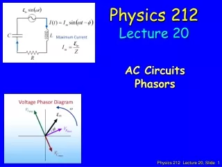
Phasers What is VC at t = p/(2w) VR VC a VL Phasor diagram at t = p/(2w) (A) (C) (B) (D) Phasor diagram at t = 0 a Voltage is equal to projection of phasor along vertical axis 65%
. Ampere’s Law Integrals Two infinitely long wires carrying current run into the page as indicated. Consider a closed triangular path that runs from point 1 to point 2 to point 3 and back to point 1 as shown. Which of the following plots best shows B·dl as a function of position along the closed path? B B The magnetic field points in the azimuthal direction and is oriented clockwise. No current is contained within the loop 1-2-3-1, therefore NOT (A) The magnetic field falls off like 1/r (r is the distance from the wire). From 3 to 1, B·dl is < 0, largest magnitude near wires. From 1 to 2, B·dl is > 0
Flux definition: Faraday’s law: 62%
The induced currents at t = 5s and t = 6s are equal 65% Current is determined by time rate of change of the flux dF/dt is determined by dB/dt dB/dt (6s) = dB/dt (5 s) = -2 T/s
Faraday’s Law Induced current must produce positive B field Positive B field produced by counterclockwise current 76% Current induced because flux is changing Flux is changing beause B is changing At t = 5 seconds, B is positive, but decreasing Lenz’ law: emf induced to oppose change that brought it into being