Download
1 / 46
460 likes | 686 Views
Universidad de Chile Department of Mechanical Engineering. Laminar unsteady flow and heat transfer in confined channel flow past square bars arranged side by side. University of Notre Dame Tuesday, December 4, 2001. Professor Alvaro Valencia. Motivation.

E N D
Universidad de Chile Department of Mechanical Engineering Laminar unsteady flow and heat transfer in confined channel flow past square bars arranged side by side University of Notre Dame Tuesday, December 4, 2001 Professor Alvaro Valencia
Motivation • Laminar flow in a channellow heat transfer • Heat transfer Enhancement in channels: Q=AhT • h with fluid mixing transverse vortex • generators Streaklines around a square bar for Re=250, and Re=1000 Davis, (1984)
Turbulent flow near a wall, Re=22000, experimental results, Bosch ( 1995) Numerical results, k- turbulence model
Anti-phase and in-phase vortex shedding around cylinders Williamson, (1985) Re=200 G/d=2.4
Wake interference of a row of normal flat plates arranged side by side in a uniform flow, Hayashi, (1986) • G/Hc=0,5 Rec=59 • G/Hc=1,0 Rec=100 • G/Hc=1,5 Rec=100 • G/Hc=2,0 Rec=100
Numerical simulation of laminar flow around two square bars arranged side by side with free flow condition. Bosch (1995) Rec=100 G/Hc=0,2 1 bar behavior
Rec=100 G/Hc=0,75 Bistable vortex shedding For G/d >1.5 synchronization of the vortex shedding in anti-phase or in-phase
Geometry of the computational domain • ReH=800 (Rec=100) • Pr=0,71 (Air) • Transverse bar separation distance, G/H or G/Hc
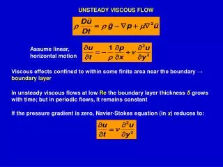
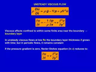
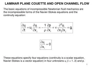
Mathematical formulation • Continuity • Navier Stokes equations (momentum) • Thermal energy The variables were non-dimensionalized with Uo, H, and To.
Boundary Conditions • Inlet: • Fully developed parabolic velocity profile • Constant temperature To Walls: Constant wall temperature Tw=2To Thermal entrance region
Boundary conditions • Outlet: wake equation to produce little reflection of the unsteady vortices at the exit plane
Numerical solution technique • Differential equations were solved with an iterative finite-volume method described in Patankar( 1980). • The convection terms were approximated using a power-law sheme • The method uses a staggered grid and handles the pressure-velocity coupling with the SIMPLEC algorithm, van Doormal (1984). • A first-order accurate fully implicit method was used for time discretization in connection with a very small time step. 1.5Uot/x=0.1 • A tipical run of 70.000 time steps with the 192x960 grid points takes about 4 days in a personal computer Pentium III.
Grid selection • The confined flow around a square bar mounted inside a plane channel was chosen for evaluate the numerical method and grid size. • A lot of data was found in the literature for the confined laminar flow past a square bar, it was found also a great dispersion of the results. • M. Breuer et al presented accurate computations of the laminar flow past a square cylinder based on two different methods, (2000). • The present numerical results were compared with their results
*: Strouhal numbers St, Drag coefficient and Lift coefficient are based here on the maximum flow veliocity
Conclusion on grid selection • The grid with 192x960 control volumes CV was chosen because delivery good results with areasonable calculation time
Cases studied • The computations were made for 11 transverse bar separation distances • Re=800 • Pr=0.71 air flow • Hc/H=1/8 bar height • L/H=5 channel length
Instantaneous local skin friction coefficient on the channel walls. Case 1Cf= / (1/2Uo**2) : wall shear stress Superior wall Inferior wall
Local skin friction coefficient on theinferior channel wall. Cases 11 to 6
Local skin friction coefficient on the channel walls.Cases 5 to 1 Inferior wall Superior wall
Local Nusselt numbers:Cases 5 to 1 Inferior wall Superior wall
Frequency: Case (2)Velocity U, Position: 2Hc behind the bar Inferior bar Superior bar
Frequency: Case (2)Velocity V, Position: 2Hc behind the bar Inferior bar Superior bar
Frequency: Case (2) Inferior bar Drag coefficients Superior bar
Frequency: Case (2) Inferior bar Lift Coefficients Superior bar
Strouhal numbers and Frequencies St=fd/Uo Struhal number F=fH/Uo non dimesional frequency F: frequency of Velocity V St=F/8
Dominant frequency of the flowlow frequency modulation in cases: G=0.0625, 0.09375, and 0.125H f G/H=0 = 1.14
Skin friction coefficient on channel wall Cf= / (1/2Uo**2) : wall shear stress
Drag coefficients for the lower and superior barCd=D/(1/2Uo**2)d Cd G/H=0 =5
Lift coefficients: lower bar, superior barCl=L/(1/2Uo**2)d
Mean Nusselt number : inferior wall and superior wall Nu=hH/k q=hT wall heat flux nu G/H=0 =11
Apparent friction factorf=PH/(Uo**2)L f G/H=0 = 0.164
Mean Heat Transfer enhancement and Pressure drop increase Nuo and fo for a plane channel without built-in square bars Nu0= 7,68 and f0= 0,01496 Nu with 1 square bar=8.52 f with 1 square bar =0.053
Conclusions • The effect of two square bars placed side by side in a laminar flow in a plane channel on pressure drop and heat transfer was numerically investigated. • The flow pattern for equal sized square bars in side-by-side arrangements were categorized into three regimes: steady flow, in-phase vortex shedding and bistable vortex shedding.
In the cases with vortex-shedding synchronization the frequency of the unsteady flow are almost four times that in the cases without synchronization of the periodic unsteady flow.
The results show that the local and global heat transfer on the channel walls are strongly increased by the unsteady vortex shedding induced by the bars.
References [1] H. Suzuki, Y. Inoue, T. Nishimura, K. Fukutani, k. Suzuki, Unsteady flow in a channel obstructed by a square rod (crisscross motion of vortex). International Journal of Heat and Fluid Flow 14 (1993) 2-9. [2] A. K. Saha, K. Muralidhar, G. Biswas, Transition and chaos in two-dimensional flow past a square cylinder, Journal of Engineering Mechanics, 126, (2000), 523-532. [3] M. Breuer, J. Bernsdorf, T. Zeiser, F. Durst, Accurate computations of the laminar flow past a square cylinder based on two different methods: lattice-Boltzmann and finite-volume, International Journal of Heat and Fluid Flow, 21, (2000), 186-196. [4] J. L Rosales, A. Ortega, J.A.C. Humphrey, A numerical simulation of the convective heat transfer in confined channel flow past square cylinders: comparison of inline and offset tandem pairs, International Journal of Heat and Mass Transfer, 44, (2001), 587-603. [5] K. Tatsutani, R. Devarakonda, J.A.C. Humphrey, Unsteady flow and heat transfer for cylinder pairs in a channel, International Journal of Heat and Mass Transfer, 36, (1993), 3311-3328. [6] A. Valencia, Numerical study of self-sustained oscillatory flows and heat transfer in channels with a tandem of transverse vortex generators, Heat and Mass Transfer, 33, (1998), 465-470. [7] D. Sumner, S.J. Price, M.P. Païdoussis, Flow-pattern identification for two staggered circular cylinders in cross-flow, Journal of Fluid Mechanics, 411, (2000), 263-303. [8] C.H.K. Williamson, Evolution of a single wake behind a pair of bluff bodies, Journal of Fluid Mechanics, 159, (1985), 1-18. [9] J.J. Miau, H.B. Wang, J.H. Chou, Flopping phenomenon of flow behind two plates placed side-by-side normal to the flow direction, Fluid Dynamics Research, 17, (1996), 311-328. [10] M. Hayashi, A. Sakurai, Wake interference of a row of normal flat plates arranged side by side in a uniform flow, Journal of Fluid Mechanics, 164, (1986), 1-25. [11] S.C. Luo, L.L. Li, D.A. Shah, Aerodynamic stability of the downstream of two tandem square-section cylinders, Journal of Wind Engineering and Industrial Aerodynamics, 79, (1999), 79-103. [12] G. Bosch, Experimentelle und theoretische Untersuchung der instationären Strömung um zylindrische Strukturen, Ph.D. Dissertation, Universität Fridericiana zu Karlsruhe, Germany, (1995). [13] S. Patankar, Numerical heat transfer and fluid flow, Hemisphere Publishing Co., New York, (1980). [14] J.P. van Doormaal, G.D. Raithby, Enhancements of the SIMPLE method for predicting incompressible fluid flows. Numerical Heat Transfer, 7, (1984), 147-163.